 English
 русский
 Português
 عربى
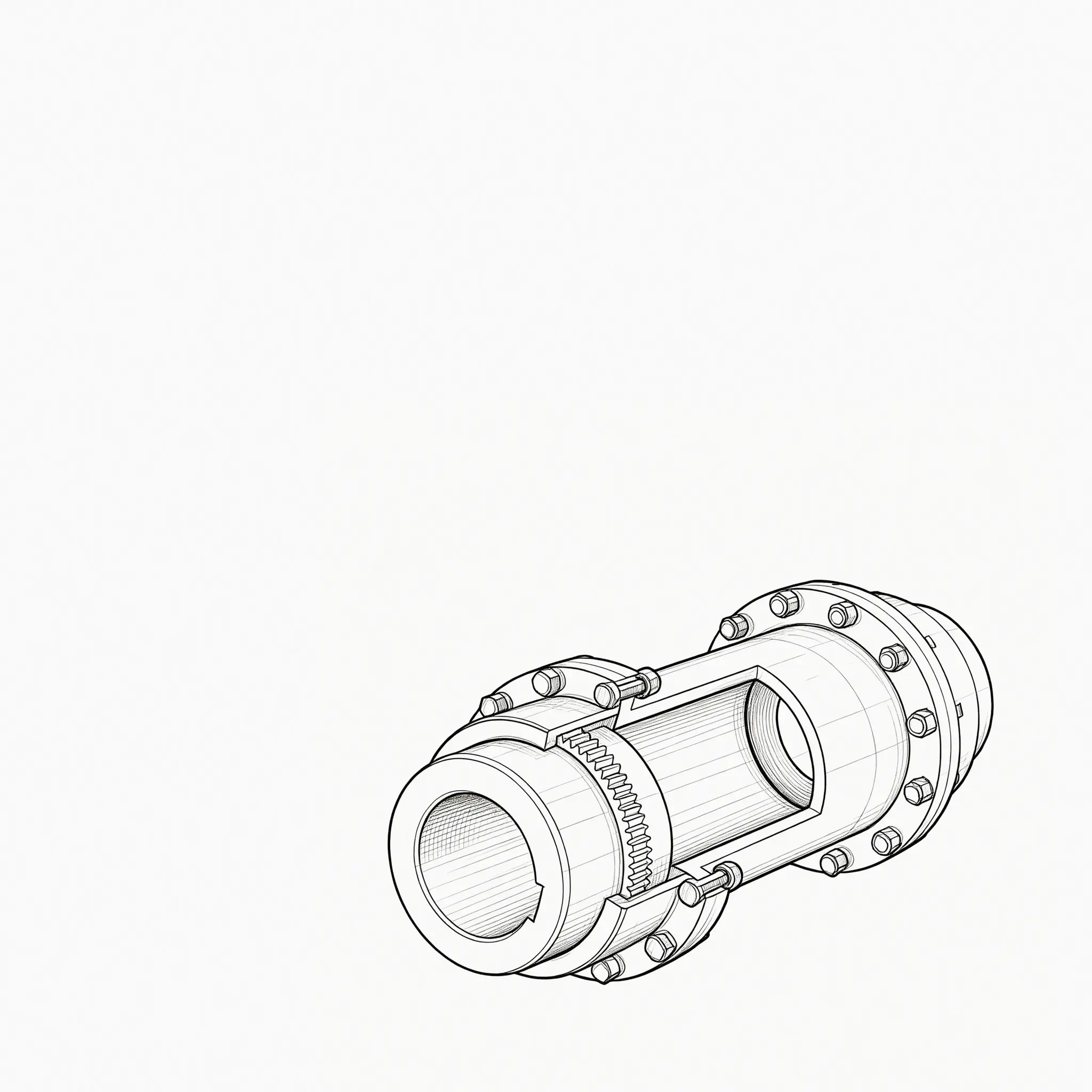
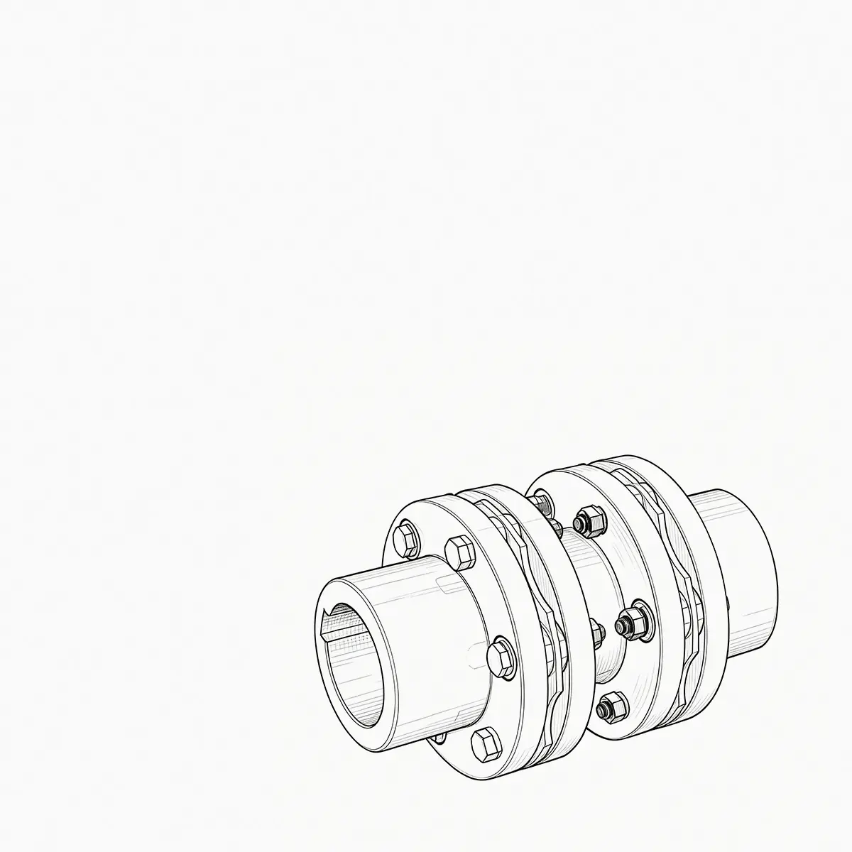
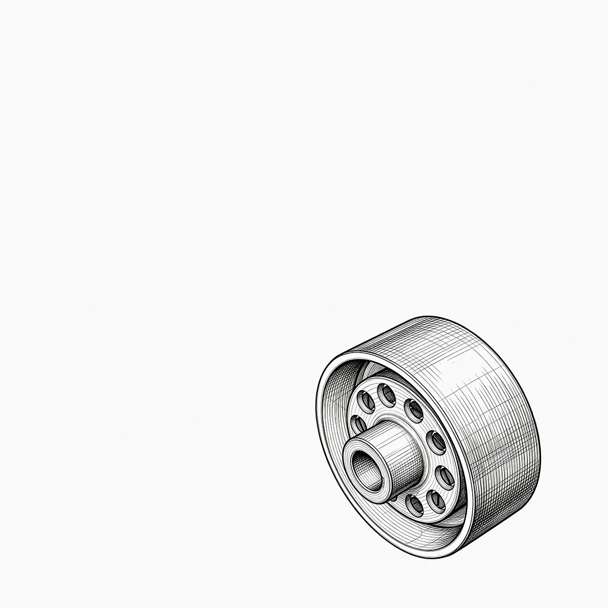
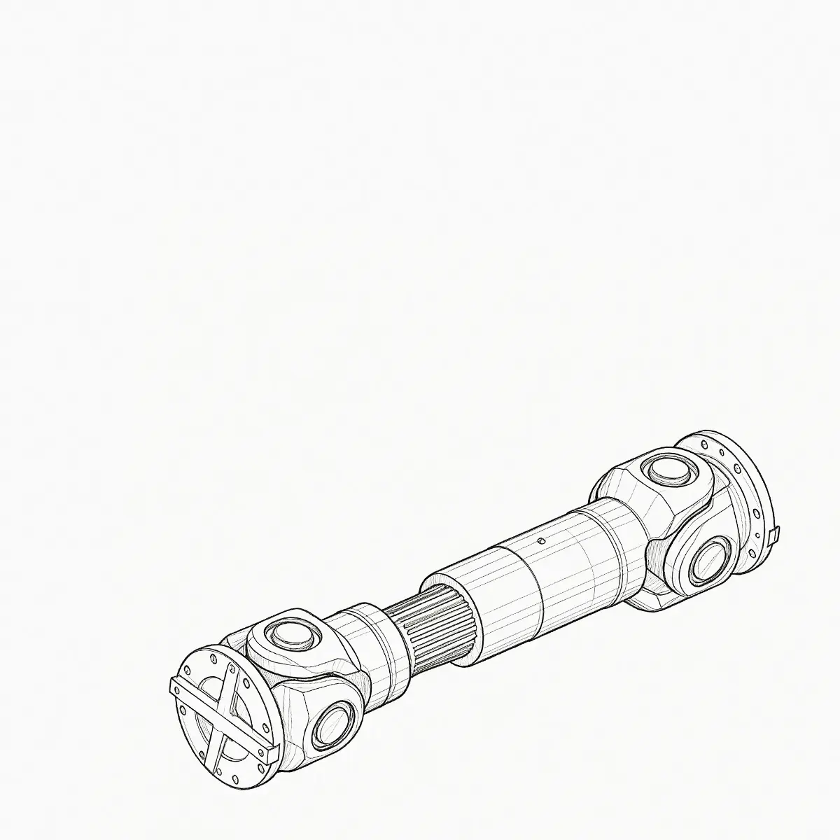
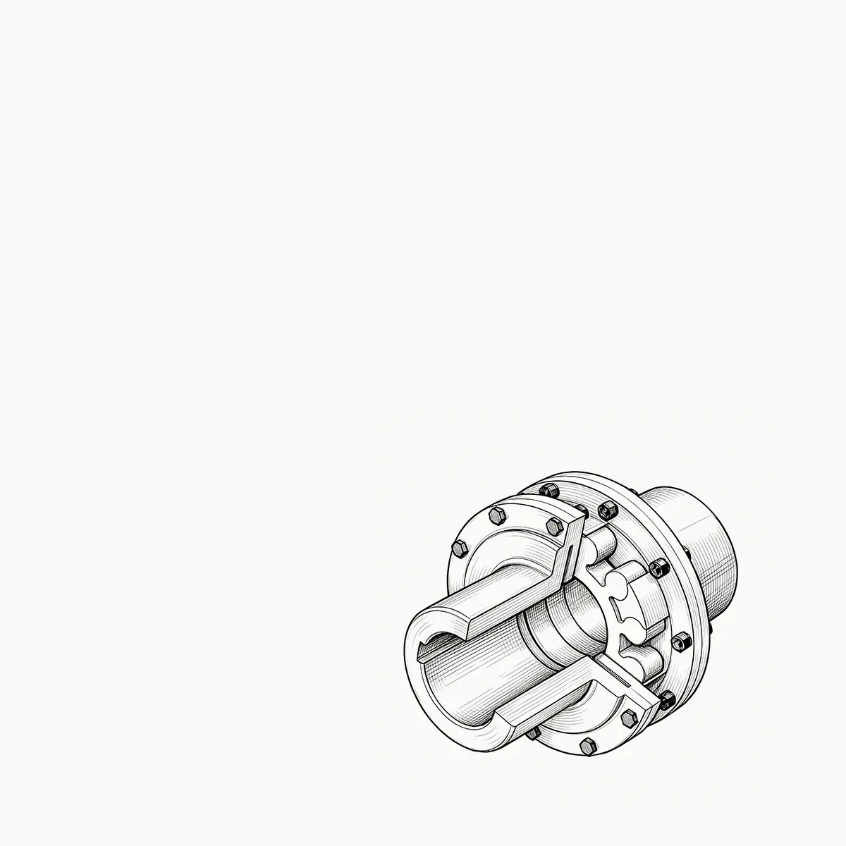
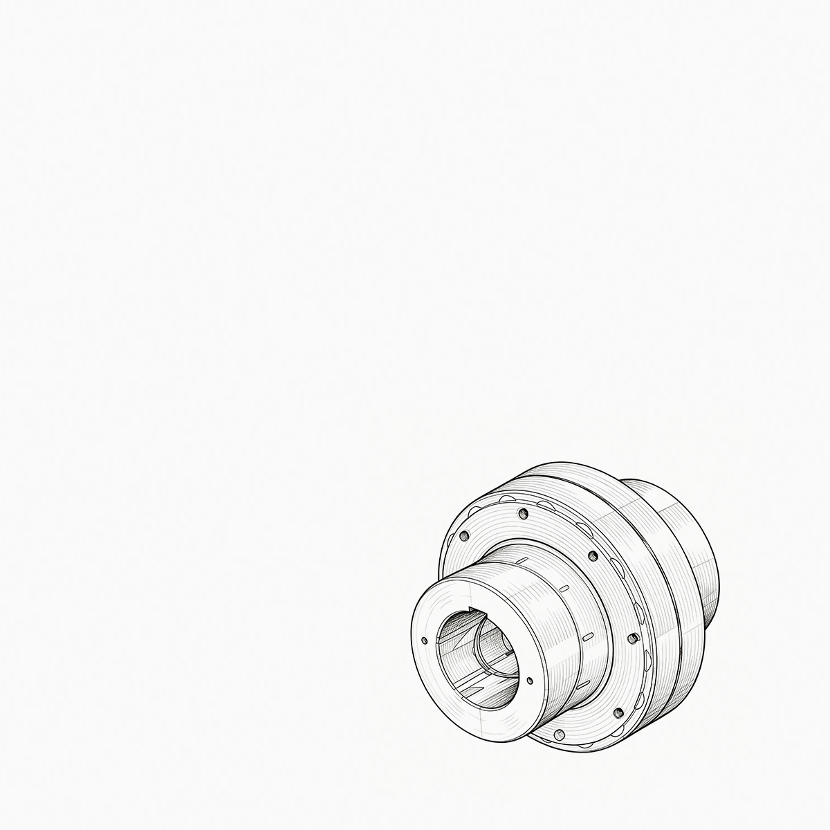
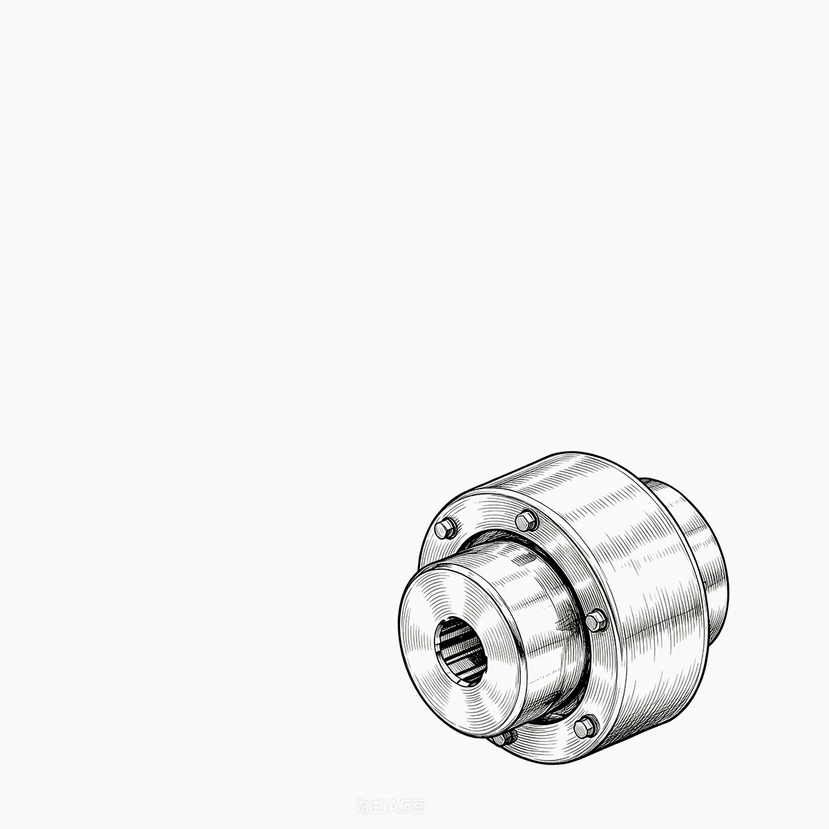
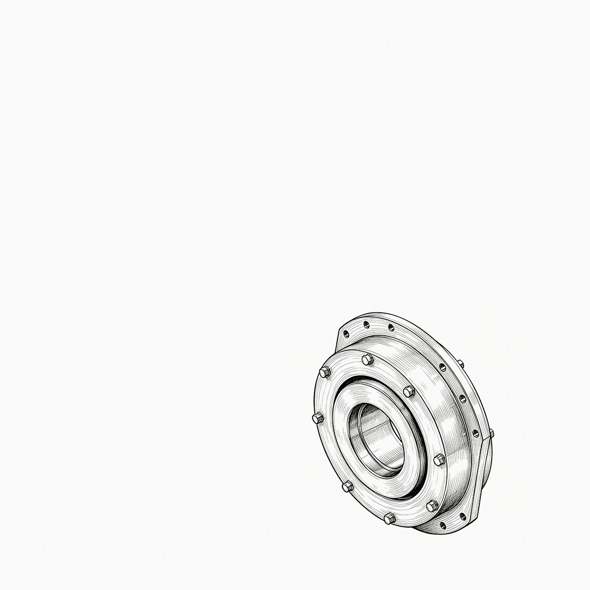
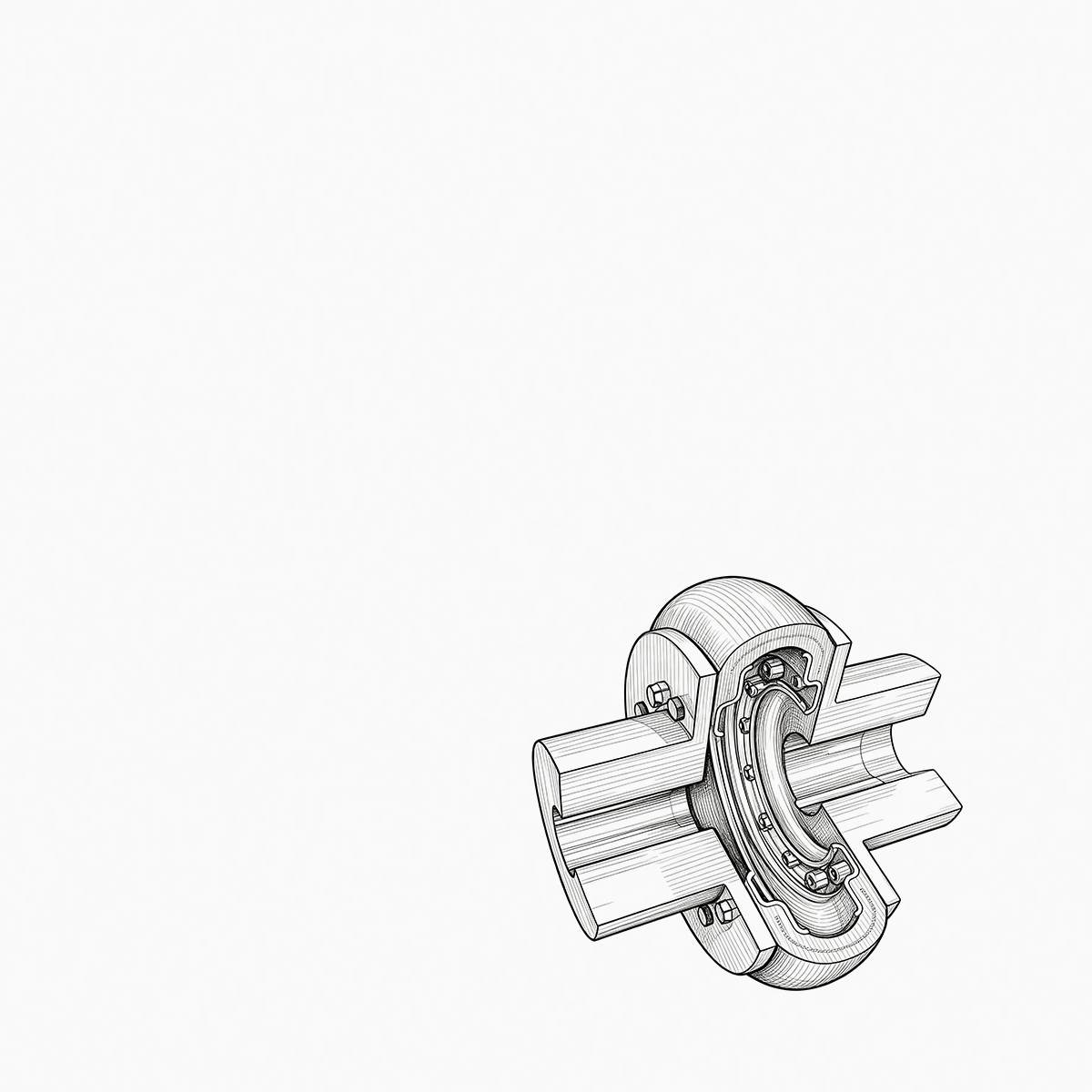

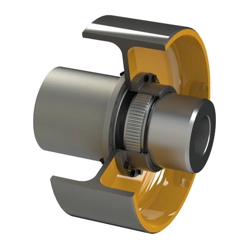
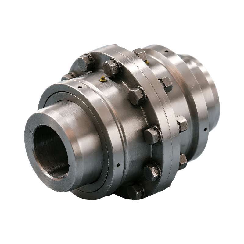
Consider a 250 kW crane hoist that begins to vibrate only when the load is lifted. The drum gear coupling is inspected ...
READ MORE
GICL Type Drum-Type Gear Coupling: Heavy-Duty Torque Transmission for Demanding Industrial Drives
Admin 2026-10-11Content
- 1 1. The Role of a Drum-Type Gear Coupling in Industrial Equipment
- 2 2. Core Construction and Operating Principle
- 3 3. Main Performance Advantages
- 3.1 3.1 High Torque Capacity in a Compact Mechanical Connection
- 3.2 3.2 Compensation for Angular, Radial, and Axial Misalignment
- 3.3 3.3 Better Load Distribution Across Multiple Teeth
- 3.4 3.4 Reduced Edge Loading and Stress Concentration
- 3.5 3.5 Improved Resistance to Heavy Loads and Impact
- 3.6 3.6 Support for Equipment Safety and Service Life
- 4 4. Advantages Compared with Alternative Coupling Types
- 5 5. Suitable Industrial Applications
- 6 6. Manufacturing Quality and Engineering Strengths
- 7 7. Selection Guidelines for the GICL Coupling
- 8 8. Installation Best Practices
- 9 9. Maintenance and Service Life Management
- 10 10. Troubleshooting Common Problems
- 11 11. Why Manufacturer Support Matters
- 12 12. Frequently Asked Questions
- 12.1 Q1: What is a GICL drum-type gear coupling?
- 12.2 Q2: What is the main difference between crowned teeth and straight teeth?
- 12.3 Q3: Is this coupling suitable for high-speed applications?
- 12.4 Q4: Can the coupling compensate for axial movement?
- 12.5 Q5: Does a flexible coupling eliminate the need for alignment?
- 12.6 Q6: What industries commonly use drum-type gear couplings?
- 12.7 Q7: What maintenance does the GICL coupling require?
- 12.8 Q8: What information is needed to select the correct coupling size?
- 12.9 Q9: Can the coupling be customized?
- 12.10 Q10: Why is lubrication so important?
- 12.11 Q11: What signs indicate possible coupling failure?
- 12.12 Q12: Why choose a gear coupling instead of an elastomeric coupling?
- 13 13. Conclusion
- 14 References
- 15 Product: GICL Type Drum-type Gear Coupling
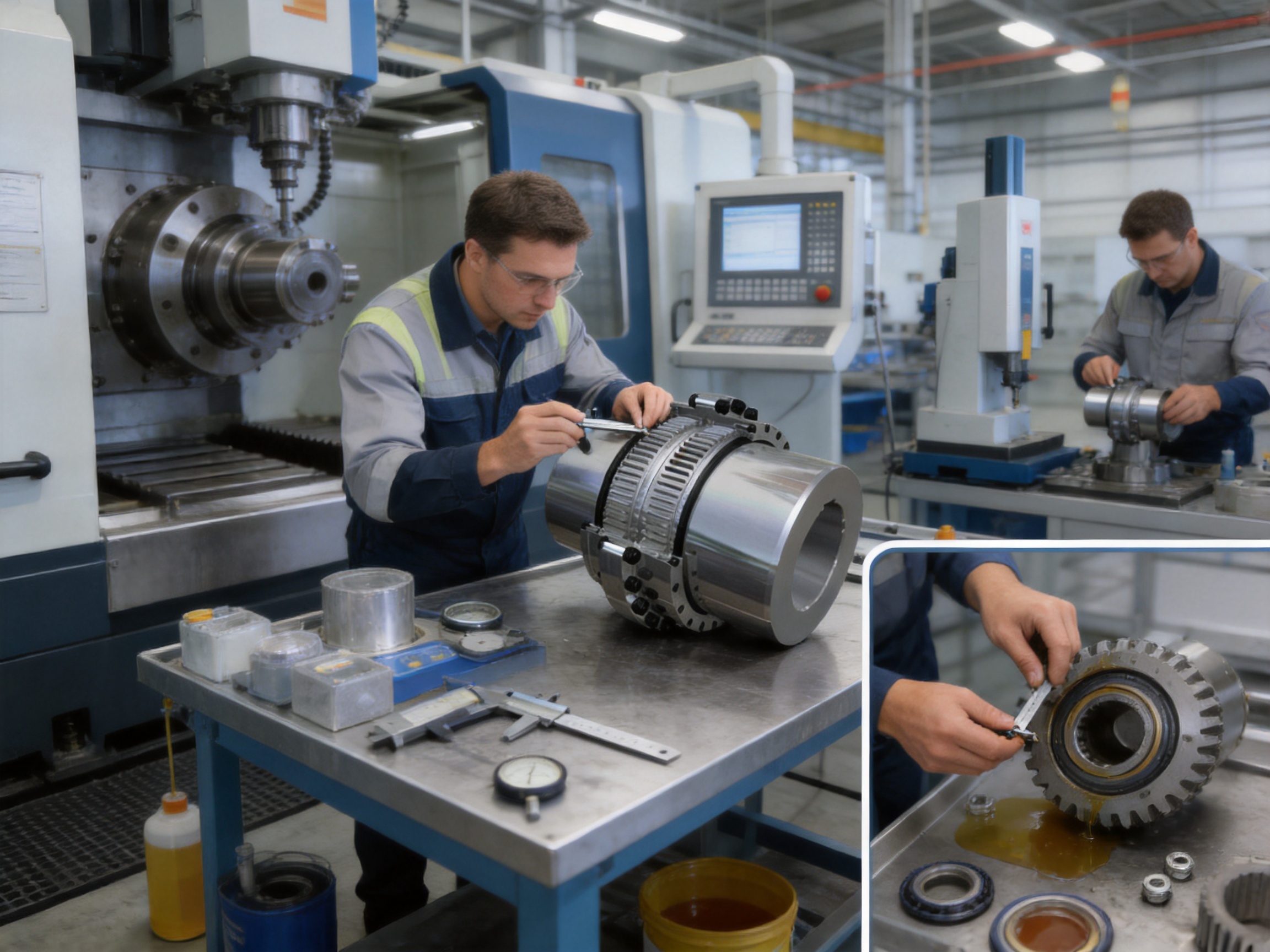
Industrial drive systems operating under high torque, low speed, impact loading, and difficult alignment conditions require more than a basic shaft connection. They need a coupling that can transmit power continuously, accommodate installation and operating movement, limit additional shaft loads, and maintain dependable performance over a long service period. The GICL type drum-type gear coupling is designed for precisely these conditions. It is a heavy-duty mechanical coupling intended for demanding applications in metallurgy, mining, lifting and transportation, construction, and other areas where drive reliability directly affects production efficiency and safety.
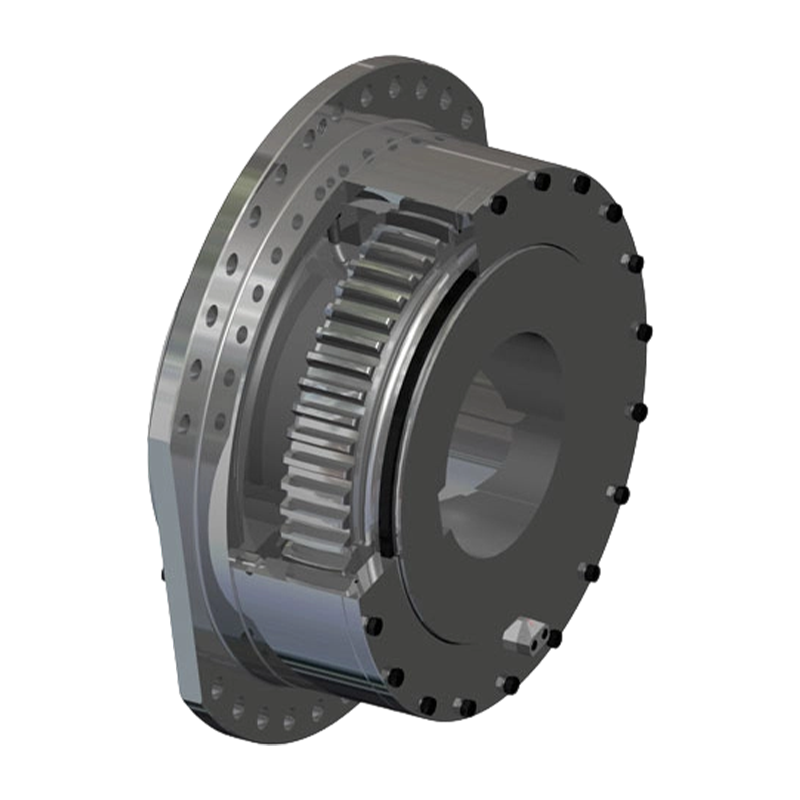
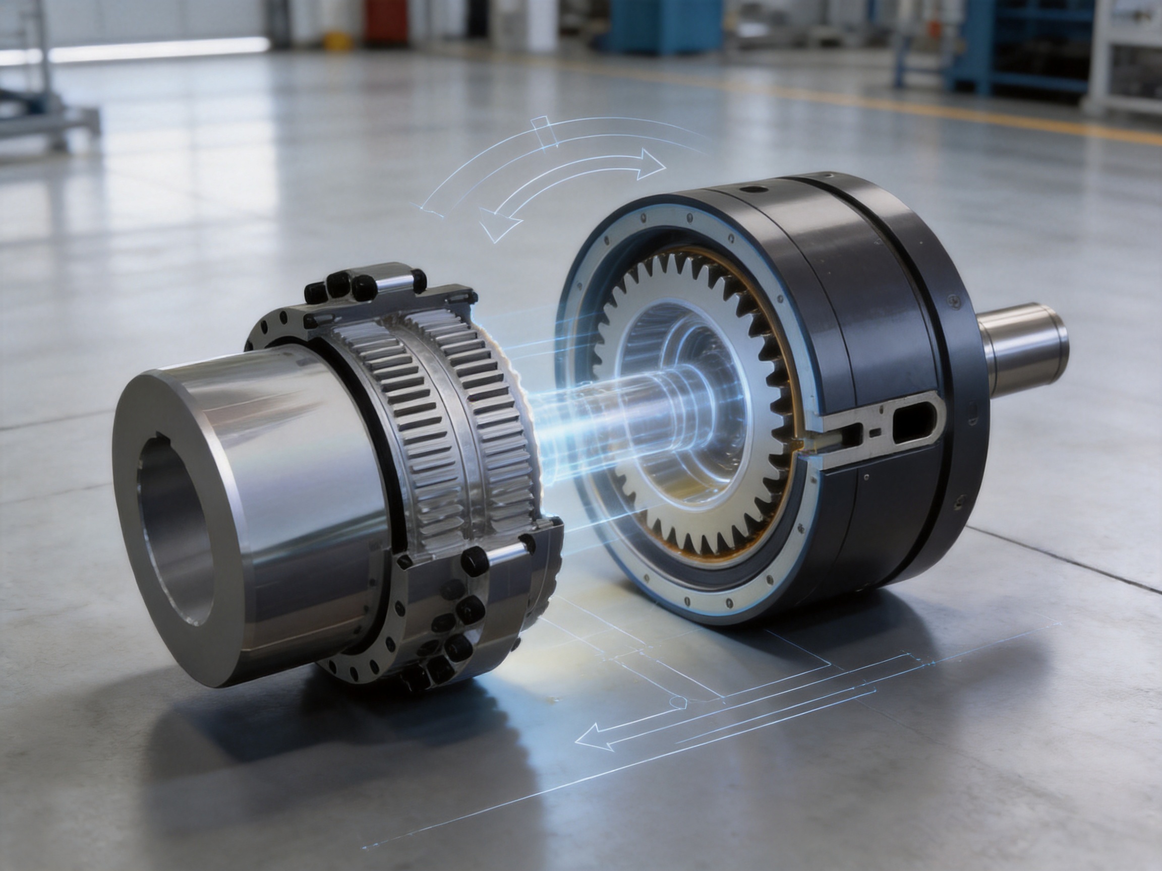
The coupling combines the high torque capacity of a gear connection with the misalignment compensation required by large industrial machines. Its primary structure consists of an internal gear hub and an external-tooth sleeve. The external gear uses a crowned tooth profile rather than a conventional straight-tooth form. This geometry allows the tooth surfaces to continue engaging effectively when the connected shafts experience angular misalignment, radial movement, axial displacement, installation deviation, or deformation during operation.
Unlike lightweight couplings designed mainly for moderate loads and limited misalignment, a drum-type gear coupling is engineered for robust power transmission. It can be integrated into drive arrangements where large motors, reducers, drums, rolls, wheels, hoisting mechanisms, or other rotating equipment must transfer substantial torque. At the same time, its flexible gear engagement helps reduce the harmful effects of unavoidable shaft movement. The result is a practical balance between strength, flexibility, durability, and serviceability.
1. The Role of a Drum-Type Gear Coupling in Industrial Equipment
A coupling connects two shafts so that rotational power can pass from one machine element to another. In a typical industrial system, the driving shaft may be connected to an electric motor or gearbox, while the driven shaft may operate a drum, conveyor, rolling mill, lifting mechanism, pump, or other heavy machine. The coupling must transmit torque while dealing with the fact that the two shafts are never perfectly aligned under all conditions.
Alignment can change because of manufacturing tolerances, foundation settlement, thermal expansion, shaft deflection, bearing clearance, structural vibration, installation error, or changes in machine loading. If a rigid connection is used in such an environment, these movements can create large additional forces. Such forces may be transmitted directly to the shafts, bearings, gears, and connected equipment. Over time, the result can include bearing wear, shaft fatigue, vibration, overheating, gear damage, and unplanned downtime.
The GICL coupling addresses this problem through a flexible gear interface. The hubs and sleeves remain mechanically engaged for positive torque transmission, while the crowned external teeth allow controlled relative movement between the connected components. This design makes the coupling especially appropriate for machines that combine heavy torque with shaft displacement.
The term “drum-type” relates to the larger, rounded, or crowned tooth geometry used on the external gear portion. Instead of relying on straight tooth flanks that may concentrate contact at an edge when the shafts are misaligned, the crowned tooth form provides a more favorable contact condition. This is particularly valuable in applications where the coupling must withstand shock loads, fluctuating torque, frequent starts and stops, or large rotating masses.
2. Core Construction and Operating Principle
2.1 Internal Gear Hub
The internal gear hub is mounted on one of the connected shafts. Its internal tooth profile meshes with the crowned external teeth of the sleeve. The hub provides the primary torque-transmitting interface and must be manufactured with accurate tooth geometry, stable dimensions, and suitable surface quality.
In a properly selected coupling, the hub is matched to the shaft arrangement through an appropriate bore, keyway, shrink fit, spline, or other connection method specified for the equipment. The shaft connection must be designed to carry the transmitted torque without slippage or excessive stress. The coupling itself cannot compensate for an undersized shaft, inadequate key, poor fit, or insufficient bearing support. Correct system design is therefore essential.
2.2 External-Tooth Sleeve
The external-tooth sleeve surrounds or engages with the gear hub. Its internal surface carries the crowned external teeth that mesh with the hub. Depending on the equipment arrangement, the sleeve can be connected to the opposite shaft or to an intermediate machine component.
The sleeve is responsible for maintaining continuous gear engagement while allowing a controlled degree of movement. Its design must provide enough tooth width and structural strength for the required torque, while also leaving suitable space for axial displacement, lubrication, assembly, inspection, and sealing.
2.3 Crowned Tooth Profile
The most important feature of the GICL drum-type gear coupling is the crowned tooth profile. The tooth surface is machined with a spherical form, with the center of the spherical geometry aligned with the coupling axis. This form differs substantially from a simple straight-sided gear tooth.
When two shafts are perfectly aligned, the tooth surfaces can engage across a broad and favorable area. When angular or radial misalignment occurs, the crowned surface permits the contact area to shift without forcing the tooth edge to carry the entire load. The design therefore helps reduce edge loading, local stress concentration, and irregular wear.
Tooth side clearance is also optimized. Adequate clearance is necessary to permit relative movement and prevent binding, but excessive clearance can increase impact, backlash, vibration, and tooth loading. The coupling’s tooth geometry is intended to maintain a practical balance between movement capacity and stable torque transfer.
2.4 Housing, Sealing, and Lubrication Considerations
Gear couplings require appropriate lubrication because their tooth surfaces operate under high contact pressure and relative movement. Lubrication reduces friction, controls wear, dissipates heat, and protects the tooth surfaces from corrosion and scuffing. The housing and sealing arrangement should therefore be selected according to the operating environment, rotational speed, temperature, and maintenance plan.
In dusty, wet, outdoor, or metallurgical environments, the sealing system is particularly important. Contamination can degrade lubricant performance and accelerate tooth wear. A suitable installation should protect the gear mesh from water, abrasive dust, scale, and other foreign material. Routine inspection should confirm that seals remain intact and that the coupling contains the correct lubricant in the proper quantity.
3. Main Performance Advantages
3.1 High Torque Capacity in a Compact Mechanical Connection
Gear couplings are valued for their ability to transmit high torque through a relatively compact connection. The torque is carried through multiple engaged teeth rather than a single friction surface or a small number of flexible elements. This multi-tooth engagement allows the coupling to support substantial industrial loads when the size and rating are correctly selected.
For low-speed, high-torque equipment, this characteristic is often more important than high rotational speed capability. Applications such as lifting drums, rolling equipment, conveyors, crushers, and heavy transport machinery frequently require a strong connection capable of handling load changes and intermittent shock. The GICL design is intended to provide the mechanical robustness needed in these operating conditions.
3.2 Compensation for Angular, Radial, and Axial Misalignment
One of the coupling’s principal advantages is its ability to accommodate several forms of misalignment. Angular misalignment occurs when the centerlines of the two shafts meet at an angle. Radial misalignment occurs when the centerlines are parallel but offset. Axial displacement occurs when the shafts move toward or away from each other along the axis.
The crowned tooth arrangement supports angular and radial movement while maintaining torque transmission. The coupling’s axial movement capability can also be useful in systems affected by thermal expansion, shaft float, structural movement, or changes in the position of connected machinery. The permitted movement must always remain within the manufacturer’s specified limits, but the ability to compensate for displacement provides an important advantage over rigid shaft connections.
When a coupling accommodates movement correctly, the connected shafts and bearings experience fewer unnecessary forces. This can help stabilize the drive system, reduce vibration, and support longer service life for surrounding components.
3.3 Better Load Distribution Across Multiple Teeth
The crowned tooth form improves the likelihood that the load will be distributed across several teeth instead of being concentrated at a tooth edge or at a small local area. More uniform load distribution lowers the risk of local overload and reduces the rate of tooth surface deterioration.
This advantage becomes especially significant under impact conditions. Heavy machinery may experience sudden torque changes when a load is picked up, a conveyor is started, a roll contacts material, or a machine encounters resistance. A coupling with favorable tooth contact can manage these changes more reliably than a connection whose load is concentrated in a narrow region.
3.4 Reduced Edge Loading and Stress Concentration
Straight-tooth gear couplings may become vulnerable to edge contact when the connected shafts are misaligned. Edge contact creates high local pressure and can lead to pitting, scoring, plastic deformation, or premature tooth failure. The crowned geometry of the GICL coupling is designed to reduce this tendency.
By allowing the tooth contact to remain more gradual as alignment changes, the coupling helps lower local stress concentration. This does not eliminate the need for accurate installation or proper maintenance, but it provides a greater tolerance for the real operating conditions encountered in large industrial machines.
3.5 Improved Resistance to Heavy Loads and Impact
Heavy-duty equipment rarely operates under perfectly smooth torque. Starting, stopping, reversing, lifting, braking, and material engagement can all create transient loads. The drum-type gear coupling is suited to these conditions because its positive gear engagement provides a strong mechanical path for torque.
Its robust construction and crowned tooth profile help the coupling withstand repeated load variation when the selected size, material, lubrication, and installation conditions are appropriate. This makes it a practical choice for machines where a flexible element must be strong enough to survive shock without sacrificing alignment compensation.
3.6 Support for Equipment Safety and Service Life
A coupling is not an isolated component. Its performance affects the shafts, bearings, gearboxes, drums, and machine frames connected to it. By accommodating movement and reducing additional shaft loads, the GICL coupling can contribute to safer and more stable operation of the complete drive train.
Reduced secondary loading may help limit bearing temperature, shaft deflection, vibration, and fatigue. These benefits can improve equipment availability and reduce the likelihood of unexpected maintenance. The coupling should not be viewed as a substitute for correct alignment or structural design, but its flexibility provides valuable protection against normal operating variation.
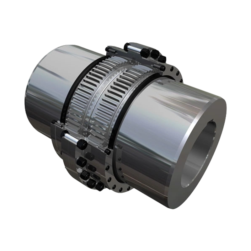
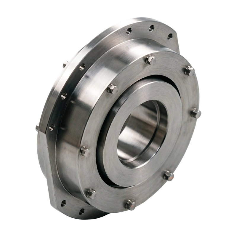
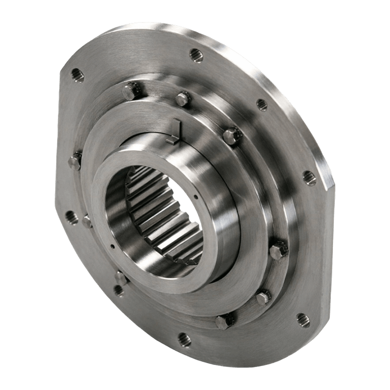
GICL Type Drum-type Gear Coupling
4. Advantages Compared with Alternative Coupling Types
4.1 Compared with Rigid Couplings
Rigid couplings connect two shafts without intentionally allowing relative movement. They can be suitable where shafts are accurately aligned and remain stable throughout operation. However, they are less tolerant of thermal growth, foundation movement, shaft deflection, and installation variation.
The GICL drum-type gear coupling offers a significant advantage where alignment cannot remain perfect. It transmits torque positively while allowing controlled angular, radial, and axial movement. This reduces the risk that alignment errors will be converted directly into harmful bearing and shaft loads.
4.2 Compared with Elastomeric Couplings
Elastomeric couplings can provide damping, electrical isolation, and convenient installation. They are often effective in light- to medium-duty drives and applications where vibration control is a major priority. However, elastomeric elements are affected by temperature, chemical exposure, aging, fatigue, and material degradation. Their torque and temperature capacity may also be lower than that required by very large industrial drives.
A gear coupling generally provides higher torque density and better suitability for heavy, continuous mechanical loading. The GICL type is particularly attractive when the application requires substantial torque transmission and misalignment compensation but does not depend primarily on elastomeric damping.
4.3 Compared with Pin and Bush Couplings
Pin and bush couplings use flexible pins and resilient elements to transmit torque. They can offer useful vibration absorption and relatively simple maintenance. Nevertheless, the flexible elements may wear under repeated shock, excessive misalignment, high temperature, or contamination. The load capacity is also dependent on the condition of the pins and bushes.
The GICL coupling uses a gear mesh rather than relying on a set of flexible bushes as the main torque path. This provides a more rigid and high-capacity connection for heavy equipment. It is therefore suitable for applications where the primary challenge is high torque and mechanical strength, while misalignment compensation remains necessary.
4.4 Compared with Diaphragm Couplings
Diaphragm couplings are valued for high-speed operation, low maintenance, and their ability to accommodate certain forms of misalignment without lubrication. They are often selected for turbines, compressors, and other precision high-speed machinery.
The GICL drum-type gear coupling is oriented toward a different duty range. Its main strengths are low-speed, high-torque transmission, heavy-load capability, and resistance to complex operating conditions. For lifting, metallurgy, mining, and large transport machinery, the gear coupling may be more appropriate than a high-speed diaphragm design.
4.5 Compared with Chain Couplings
Chain couplings are mechanically simple and can transmit moderate to high torque. However, they may produce more clearance-related impact, require effective guarding, and be sensitive to lubrication and contamination. Their ability to manage certain misalignment conditions may also be more limited depending on the design.
The enclosed gear arrangement of a drum-type coupling can provide a more integrated and stable connection. With appropriate sealing and lubrication, it is well suited to industrial equipment that requires reliable continuous torque transmission in a protected housing.
4.6 Comparison Summary
| Performance consideration | GICL drum-type gear coupling | Rigid coupling | Elastomeric coupling | Pin and bush coupling |
|---|---|---|---|---|
| High torque transmission | Very suitable for heavy industrial drives | Suitable if alignment is highly stable | Depends strongly on elastomer size and material | Suitable within element and pin limits |
| Angular and radial compensation | Provided through crowned gear engagement | Very limited | Generally good within rated limits | Good within rated limits |
| Axial displacement capacity | Useful for systems with shaft movement | Normally limited | Depends on design | Depends on design |
| Impact and shock resistance | Strong when correctly selected | Can transfer shock directly to the system | May absorb shock but can fatigue under severe duty | Flexible elements may wear under repeated impact |
| Typical maintenance focus | Lubrication, seals, tooth inspection, alignment | Alignment and fasteners | Element condition and temperature | Pin, bush, lubrication, and alignment |
| Typical application emphasis | Low-speed, high-torque, heavy machinery | Precisely aligned shafts | Vibration damping and moderate industrial duty | General industrial power transmission |
5. Suitable Industrial Applications
5.1 Metallurgical Equipment
Metallurgical production lines contain large rotating equipment, rolling stands, transfer systems, cooling beds, conveyors, and lifting mechanisms. These machines operate under high loads and may experience frequent acceleration, deceleration, impact, and thermal variation.
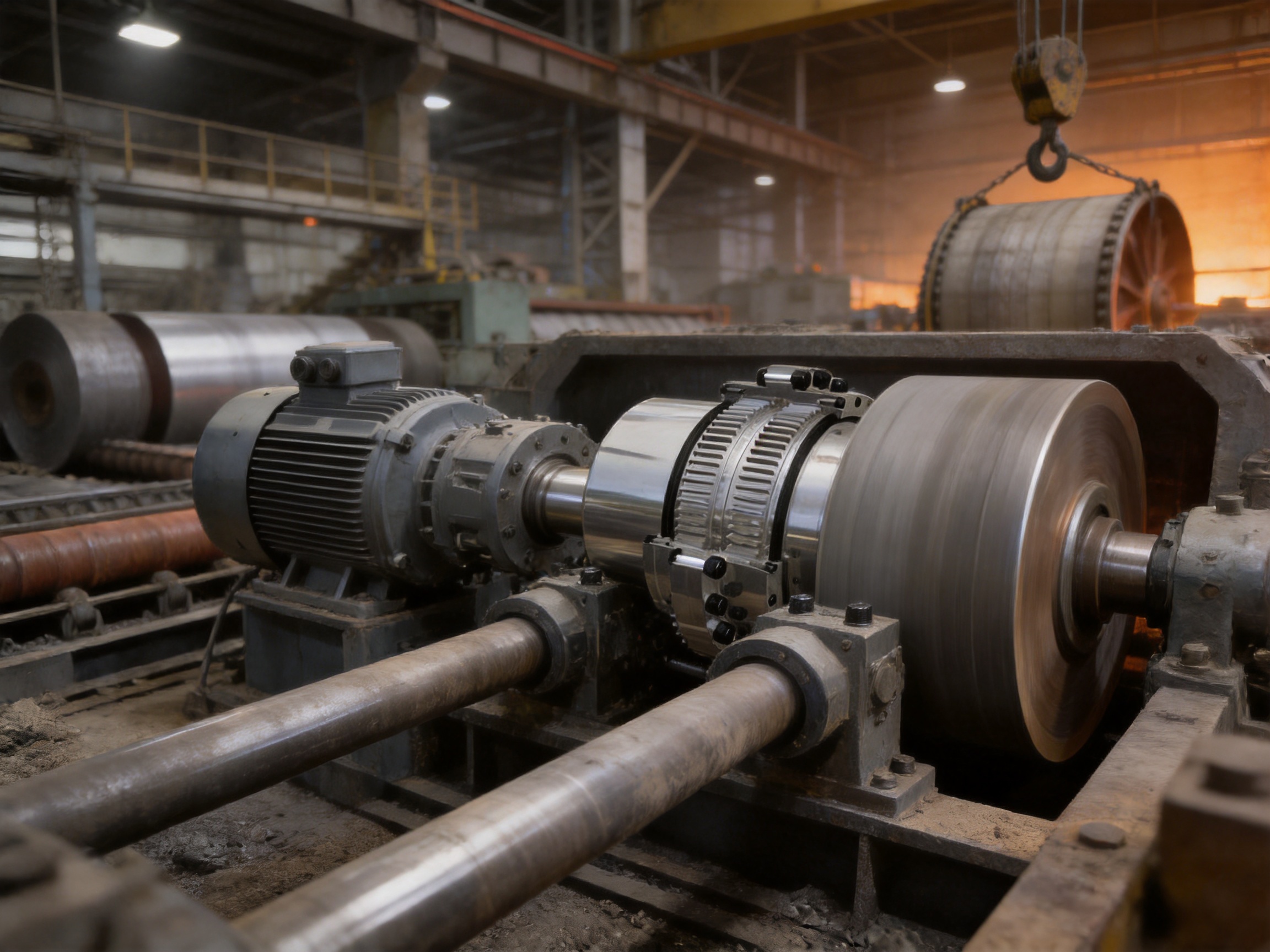
A drum-type gear coupling can connect motors, reducers, rolls, and other drive components while accommodating movement caused by machine deformation and thermal conditions. Its robust gear engagement is appropriate for the demanding torque and shock characteristics of metallurgical service.
5.2 Mining Machinery
Mining equipment must operate in environments containing dust, vibration, uneven foundations, and severe load variation. Crushers, conveyors, hoists, winches, and material-handling systems may be exposed to high starting torque and abrupt resistance changes.
The GICL coupling can support these systems by providing a strong torque path and controlled flexibility. Proper sealing, lubrication, guarding, and inspection are especially important in mining applications because abrasive contamination can accelerate wear.
5.3 Lifting and Hoisting Equipment
Lifting machinery places special demands on drive components. The system may start and stop frequently, reverse direction, hold suspended loads, and experience transient torque during lifting or braking. Reliability is essential because coupling failure can affect the operation and safety of the complete machine.
The drum-type gear coupling is suitable for selected hoisting and lifting drives where high torque, compact construction, and tolerance of shaft movement are required. The coupling must be selected with suitable service factors for starting, braking, impact, duty cycle, and load classification.
5.4 Transportation and Conveyor Systems
Large conveyors, transfer equipment, and industrial transportation systems often use low-speed, high-torque drives. The shafts may be separated by a considerable distance or connected through gearboxes and drums. Misalignment can arise from structural movement, bearing wear, or changes in the loaded condition.
The GICL coupling provides a dependable connection for these systems while helping to reduce the effects of alignment variation. Its application can contribute to stable power transfer and lower stress on the adjacent drive components.
5.5 Construction and Heavy Machinery
Construction machinery frequently operates under changing loads, vibration, and rough environmental conditions. Winches, mixers, crushers, hoists, and other heavy machines need couplings that can withstand mechanical shock and maintain serviceability.
Where the operating speed and torque range match the coupling’s design, a drum-type gear coupling can provide the required mechanical strength and movement compensation. Its use should be combined with a properly protected housing and a maintenance plan suited to outdoor or contaminated environments.
6. Manufacturing Quality and Engineering Strengths
The performance of a gear coupling depends heavily on manufacturing accuracy. The crowned tooth profile must be formed consistently, the tooth spacing must be controlled, and the components must maintain correct concentricity and dimensional stability. Small errors in tooth geometry or assembly can affect contact conditions, vibration, and service life.
Zhenjiang Orienthold Machinery Co., Ltd. specializes in the production of couplings and papermaking machinery, integrating design, production, and service. The company operates as a medium-sized industrial manufacturer with technical capabilities, production equipment, and testing resources intended to support customized mechanical products.
Its product range covers multiple coupling categories, including drum gear couplings, diaphragm couplings, elastic sleeve pin couplings, cross universal couplings, plum elastic couplings, elastomeric pin couplings, elastomeric pin gear couplings, crane drum couplings, and tire couplings. This broad product experience helps the engineering team evaluate different transmission requirements instead of treating every application as a standard product selection.
6.1 Integrated Design and Production
An integrated design and production process improves communication between engineering, machining, assembly, and inspection. For a gear coupling, this is important because tooth geometry, shaft interface, housing dimensions, sealing arrangement, lubrication method, and installation requirements must work together.
Integrated production also supports customization. Industrial users may require special bore dimensions, keyways, flange arrangements, axial travel, material options, protective housings, or connection details. A manufacturer with design and production capabilities can review these requirements as a complete system rather than supplying an isolated component without considering the machine environment.
6.2 Precision Machining of Gear Components
The external crowned teeth and internal gear teeth are the functional heart of the coupling. Precision machining is required to achieve the intended spherical tooth form, tooth clearance, alignment, and surface quality. Controlled machining helps the teeth engage smoothly and distribute load effectively.
After machining, dimensional inspection should verify bore size, tooth geometry, concentricity, face dimensions, and other critical characteristics. These controls are particularly important for large couplings, where small angular or dimensional deviations can produce meaningful contact changes during operation.
6.3 Materials and Heat Treatment Considerations
Material selection must correspond to torque, impact, operating speed, environment, and expected service life. Gear hubs and sleeves require materials with adequate strength, toughness, wear resistance, and dimensional stability. Depending on the design and customer requirements, heat treatment may be used to improve the mechanical properties of gear components.
Heat treatment must be controlled carefully. Excessive hardness can reduce toughness, while insufficient hardness may accelerate tooth wear. The correct balance depends on the coupling size, tooth loading, operating conditions, and design standard. A professional manufacturing process should connect material selection, heat-treatment control, machining, and final inspection.
6.4 Inspection and Testing
Complete inspection and testing equipment supports consistent product quality. Typical quality checks for a coupling may include dimensional inspection, visual inspection, tooth surface examination, bore and keyway verification, runout measurement, concentricity checks, and confirmation of material or heat-treatment records where applicable.
Testing requirements can vary according to the application. Heavy machinery used in lifting, metallurgy, or mining may justify additional inspection controls because failure consequences and replacement costs are significant. A manufacturer able to provide inspection documentation and technical communication gives users greater confidence when integrating the coupling into critical equipment.
6.5 Compliance with National Standards
The company states that its products comply with national standards. Standards provide a consistent basis for dimensions, performance expectations, materials, inspection, and interchangeability. Compliance does not replace application engineering, but it establishes a disciplined framework for production and quality control.
For international customers, technical documentation should be reviewed to confirm the applicable standard, rated torque, allowable speed, misalignment capacity, lubrication requirements, and installation conditions. Clear documentation helps engineering teams compare products and make informed decisions.
6.6 Customization and Technical Service
Industrial coupling applications are often not identical. A customer may need a special shaft diameter, different installation arrangement, unusual axial movement, nonstandard mounting space, modified sealing, or a coupling adapted to an existing machine. Customization can reduce the need for extensive machine modification and simplify replacement of an existing coupling.
Orienthold Machinery provides pre-sales consultation and customization support. This service is valuable when the customer does not have complete coupling data or when the equipment operates under unusual loads. The correct selection process should consider transmitted power, speed, torque, shock factor, shaft diameter, bore length, misalignment, temperature, environment, duty cycle, and maintenance access.
7. Selection Guidelines for the GICL Coupling
7.1 Determine the Required Torque
The first step is to determine the nominal torque and peak torque transmitted by the drive. Motor power and speed can be used to estimate nominal torque, but the selection should not rely on nominal torque alone. Starting, braking, reversing, jamming, material engagement, and load fluctuation can create substantially higher transient loads.
A suitable service factor should be applied according to the equipment type and operating conditions. Heavy impact service normally requires a larger safety margin than smooth, continuous operation. The selected coupling should have adequate rated torque and peak torque capacity for the complete duty cycle.
7.2 Check Speed and Rotational Balance
Although the GICL type is primarily associated with low-speed, high-torque machinery, the actual operating speed must still be checked. The coupling should operate within its rated speed range, and the assembly should be sufficiently balanced for the application.
Higher speed increases the effect of imbalance, clearance, lubrication condition, and installation error. If the coupling is used at a speed different from the normal low-speed range, the manufacturer should review the design and balance requirements.
7.3 Confirm Shaft Dimensions
Shaft diameter, bore length, keyway dimensions, shaft extension, and available installation space must be verified before ordering. The shaft connection must be capable of carrying the transmitted torque and resisting the expected reversing or impact loads.
The coupling should not be forced onto a shaft by hammering, nor should installation create damage to the bore, keyway, seal, or gear teeth. Proper fits, lifting methods, and assembly tools are important for large and heavy couplings.
7.4 Evaluate Misalignment
The allowable angular, radial, and axial displacement must be compared with the actual machine conditions. The coupling’s flexibility is valuable, but it is not unlimited. Excessive misalignment can still overload the teeth, increase wear, and reduce service life.
Initial alignment should be performed carefully even when a flexible coupling is used. A coupling is intended to accommodate operating movement, not to compensate for careless installation. Better initial alignment generally results in lower tooth pressure, smoother operation, and longer maintenance intervals.
7.5 Consider the Environment
Temperature, dust, water, chemicals, vibration, outdoor exposure, and washdown conditions should be considered during selection. The sealing arrangement, lubricant, material protection, and maintenance frequency should reflect the environment.
In mining and metallurgical plants, abrasive dust and scale may be major concerns. In outdoor lifting equipment, moisture and temperature variation may affect seals and lubricant. In chemical environments, lubricant and seal compatibility must be evaluated before installation.
7.6 Allow for Maintenance Access
The coupling should be installed where inspection, lubrication, seal replacement, and component removal are practical. If the housing is inaccessible, routine maintenance may be neglected, increasing the risk of tooth damage and unexpected failure.
Maintenance access should be considered during equipment design rather than after installation. Inspection ports, removable guards, correct clearances, and lifting provisions can significantly reduce service time.
8. Installation Best Practices
Before installation, inspect all coupling parts for transport damage, corrosion, contamination, or dimensional problems. Confirm that the coupling model, bore dimensions, keyways, fasteners, seals, and accessories match the equipment drawings and purchase specifications.
Clean the shafts and coupling bores carefully. Remove burrs, dirt, excess paint, and corrosion products. Check shaft runout and confirm that the bearings and supporting structures are in acceptable condition. A coupling cannot operate correctly if the connected shafts are bent or if the bearings have excessive clearance.
Install the hubs and sleeves according to the approved assembly procedure. Avoid striking gear teeth, sealing surfaces, or precision bores with uncontrolled impact. Use suitable heating or hydraulic methods if required by the fit. Ensure that keys are correctly fitted and do not prevent the hub from seating properly.
Align the connected shafts using appropriate measurement equipment. Check angular and parallel alignment in several rotational positions. Confirm that the coupling has the required axial position and that the intended movement is not blocked by adjacent components.
Apply the specified lubricant in the correct quantity. Too little lubricant can cause excessive friction and wear, while too much may increase churning, temperature, or seal pressure. Install the housing and seals correctly, and verify that fasteners are tightened according to the approved procedure.
After installation, rotate the assembly manually where possible. Check for binding, abnormal resistance, interference, and unusual clearance. During initial operation, monitor vibration, temperature, noise, leakage, and fastener condition. Early observation can identify installation problems before they develop into serious damage.
9. Maintenance and Service Life Management
9.1 Lubrication Control
Lubrication is one of the most important maintenance requirements for a gear coupling. The lubricant must be compatible with the tooth surfaces, seals, operating temperature, and speed. The service interval should be established according to the operating environment and duty cycle.
Inspect for lubricant leakage, contamination, discoloration, metal particles, or changes in consistency. These signs may indicate seal failure, tooth wear, overheating, or internal damage. Lubricant should be replenished or replaced according to the approved maintenance plan rather than only after abnormal noise appears.
9.2 Tooth and Seal Inspection
Inspect tooth surfaces for pitting, scoring, wear steps, cracks, plastic deformation, or unusual contact patterns. Wear concentrated at one side of the tooth may indicate excessive misalignment, inadequate lubrication, shaft deflection, or improper assembly.
Seals should be inspected for hardening, cracking, deformation, or leakage. A damaged seal can allow abrasive particles or water to enter the gear mesh. Replacing a low-cost seal promptly may prevent far more expensive gear and shaft damage.
9.3 Vibration and Temperature Monitoring
Changes in vibration, noise, and temperature can provide early warning of coupling problems. Increased vibration may result from misalignment, imbalance, tooth wear, looseness, bearing problems, or insufficient lubrication. Rising temperature may indicate friction, excessive loading, seal problems, or lubricant deterioration.
Trend monitoring is more useful than relying on a single measurement. Establish normal operating values after commissioning, then compare future readings against those values. Sudden changes should be investigated before the equipment continues under full load.
9.4 Inspection after Abnormal Events
The coupling should be inspected after overload, motor stall, emergency braking, severe vibration, collision, or other abnormal events. Even if the machine continues to operate, the tooth surfaces, keys, fasteners, housing, and shafts may have sustained hidden damage.
Early inspection helps determine whether the coupling can return to service or requires repair or replacement. This is especially important in lifting and hoisting equipment, where the consequences of undetected damage can be severe.
10. Troubleshooting Common Problems
10.1 Excessive Noise
Abnormal clicking, grinding, or knocking may indicate insufficient lubrication, excessive backlash, tooth wear, contamination, loose components, or misalignment. Stop the equipment safely and inspect the coupling rather than assuming that noise is normal.
10.2 Overheating
Overheating may be caused by insufficient lubricant, excessive lubricant, high misalignment, seal friction, overload, or operation above the rated speed. Check the operating conditions, lubricant condition, tooth contact, and alignment.
10.3 Accelerated Tooth Wear
Rapid tooth wear commonly results from poor alignment, inadequate lubrication, contamination, excessive torque, shock loading, or an incorrect coupling size. A detailed inspection should examine the wear pattern, not just the amount of material removed.
10.4 Leakage
Lubricant leakage may be caused by damaged seals, incorrect assembly, excessive internal pressure, housing damage, or unsuitable lubricant. Continued operation with low lubricant can result in rapid tooth failure. Seal and housing problems should be corrected promptly.
10.5 Repeated Fastener Loosening
Fasteners that repeatedly loosen may indicate vibration, incorrect tightening, inadequate locking, housing distortion, or misalignment. The complete installation should be reviewed instead of simply tightening the same fastener repeatedly.
11. Why Manufacturer Support Matters
Choosing a coupling only by shaft diameter can lead to an unsuitable result. A professional supplier should evaluate torque, speed, duty cycle, shock, misalignment, temperature, environment, and installation restrictions together. This approach helps ensure that the coupling is selected for the actual machine rather than for one isolated dimension.
Orienthold Machinery combines product design, manufacturing, testing, and service. Its experience with multiple coupling types allows it to recommend a suitable solution when a customer is comparing gear, diaphragm, elastomeric, pin, universal, or tire coupling designs.
The company serves industries including transportation, metallurgy, chemical engineering, mining, construction, and hoisting. Its one-stop service model includes pre-sales consultation, customization, logistics and payment coordination, and maintenance support. Such support can be valuable for international equipment manufacturers, replacement-part buyers, and plant maintenance departments.
Technical communication should include drawings, operating data, installation requirements, inspection criteria, and replacement recommendations. When these details are clearly exchanged, the supplier can provide a more accurate product and the customer can reduce installation and commissioning risks.
12. Frequently Asked Questions
Q1: What is a GICL drum-type gear coupling?
A GICL drum-type gear coupling is a heavy-duty flexible gear coupling used to connect shafts and transmit torque. It consists primarily of an internal gear hub and an external-tooth sleeve. Its crowned external teeth allow the coupling to accommodate angular, radial, and axial movement while maintaining positive mechanical engagement.
Q2: What is the main difference between crowned teeth and straight teeth?
Crowned teeth have a spherical or rounded profile designed to maintain more favorable contact when the shafts are not perfectly aligned. Straight teeth can experience concentrated edge loading under angular or radial misalignment. The crowned profile helps distribute the load more evenly and reduce local stress concentration.
Q3: Is this coupling suitable for high-speed applications?
The GICL type is mainly intended for low-speed, high-torque, heavy-duty applications. The actual allowable speed depends on the coupling size, design, balance, lubrication, and operating conditions. Speed suitability should be confirmed from the technical specification before use.
Q4: Can the coupling compensate for axial movement?
Yes, the design can accommodate a degree of axial displacement, which is useful when shafts move because of thermal expansion, structural movement, or operating conditions. The permitted axial travel must remain within the manufacturer’s specified range.
Q5: Does a flexible coupling eliminate the need for alignment?
No. A flexible coupling compensates for limited operating misalignment; it does not correct poor installation. Accurate initial alignment reduces tooth loading, vibration, and wear and is essential for achieving a long service life.
Q6: What industries commonly use drum-type gear couplings?
Typical applications include metallurgy, mining, lifting and hoisting, transportation, construction, material handling, conveyors, heavy machinery, and other industrial drive systems requiring high torque and reliable operation under complex conditions.
Q7: What maintenance does the GICL coupling require?
Maintenance normally includes lubrication inspection and replenishment, seal inspection, tooth surface examination, alignment checks, fastener inspection, and monitoring of noise, vibration, and temperature. The exact interval depends on the operating environment and duty cycle.
Q8: What information is needed to select the correct coupling size?
Important information includes motor power, operating speed, nominal and peak torque, shaft diameters, bore lengths, keyway details, axial movement, angular and radial misalignment, duty cycle, shock loads, ambient temperature, contamination, installation space, and maintenance requirements.
Q9: Can the coupling be customized?
Customization may be possible for bore dimensions, keyways, mounting arrangements, sealing, axial requirements, materials, and other application details. The manufacturer should review drawings and operating data before confirming a customized design.
Q10: Why is lubrication so important?
Lubrication reduces friction and wear between the gear teeth, limits heat generation, protects against corrosion, and helps maintain smooth engagement. Incorrect lubricant quantity or poor sealing can significantly reduce coupling service life.
Q11: What signs indicate possible coupling failure?
Warning signs include abnormal noise, increasing vibration, overheating, lubricant leakage, metal particles in the lubricant, excessive backlash, uneven tooth wear, loose fasteners, and visible damage to seals or housing. These conditions should be investigated promptly.
Q12: Why choose a gear coupling instead of an elastomeric coupling?
A gear coupling is often preferred when high torque capacity, heavy-load strength, and tolerance of industrial shock are more important than elastomeric damping. The best choice depends on speed, torque, misalignment, temperature, vibration, and environmental requirements.
13. Conclusion
The GICL type drum-type gear coupling is designed for industrial applications where dependable torque transmission must be combined with tolerance for shaft movement. Its internal gear hub, external-tooth sleeve, crowned tooth profile, and optimized side clearance provide a strong and flexible connection for low-speed, high-torque machinery.
Its principal advantages include high torque capacity, improved load distribution, compensation for angular, radial, and axial misalignment, reduced edge loading, resistance to impact, and support for longer service life of the connected drive system. These characteristics distinguish it from rigid couplings and make it a strong alternative to elastomeric, pin and bush, chain, or high-speed diaphragm coupling designs when heavy-duty mechanical performance is the primary requirement.
Successful application depends on more than the coupling itself. Correct sizing, accurate shaft alignment, suitable lubrication, effective sealing, proper installation, and regular inspection are essential. When these factors are controlled, the coupling can contribute to stable operation and reduced maintenance risk in metallurgy, mining, lifting, transportation, construction, and other demanding industries.
With integrated design, production, testing, customization, and service capabilities, Zhenjiang Orienthold Machinery Co., Ltd. is positioned to support both standard and specialized coupling requirements. Its manufacturing experience across several coupling categories allows customers to receive application-oriented advice rather than a product selected only by basic dimensions. For industrial users seeking a robust shaft connection for high torque and complex operating conditions, the GICL drum-type gear coupling offers a practical and durable engineering solution.
References
1. General principles of industrial shaft coupling selection, torque rating, service factors, and alignment practice.
2. General engineering guidance for gear coupling tooth contact, lubrication, sealing, and maintenance.
3. Industrial power transmission practice for metallurgy, mining, lifting, conveying, and heavy machinery applications.
4. National standards and manufacturer specifications applicable to industrial gear couplings and flexible shaft couplings.
5. Manufacturer technical information concerning GICL type drum-type gear couplings, crowned tooth geometry, customization, inspection, and service support.
Product: GICL Type Drum-type Gear Coupling
PREV: No previous articleNEXT: LX(HL) Elastic Pin Coupling: Reliable Torque Transmission for Industrial Machinery
Be the First to Know
For exclusive deals and latest offers, sign up by entering your email address below.
Related products
News
-
-
A mill drive rarely fails without warning. It knocks at speed, throws a smear of dark grease around the sleeve flange, ...
READ MORE -
Gear Coupling vs. Drum Gear Coupling: The Core Difference The main difference is that "gear coupling" is a broad catego...
READ MORE -
Two quotes land for the same replacement gear coupling: $1,850 from one shop and $2,600 from another. Both promise stan...
READ MORE -
Industrial Couplings: The Definitive Technical Encyclopedia – Classification, Sizing, Failure Prevention, and Lifecycle...
READ MORE -
Your compressor train is running at 9,800 rpm when the vibration monitor triggers an alarm. The first component your ma...
READ MORE


ABOUT US
PRODUCTS
INDUSTRIES
CONTACT US
- Phone: +86-18652865511
- Email: sales@ohmach.com
- Address: No.1, Minying Developing Zone, Zhenjiang, Jiangsu, China
Copyright Zhenjiang Orienthold Machinery Co., Ltd. All Rights Reserved.
 Custom Industrial Shaft Coupling Manufacturers