 English
 русский
 Português
 عربى

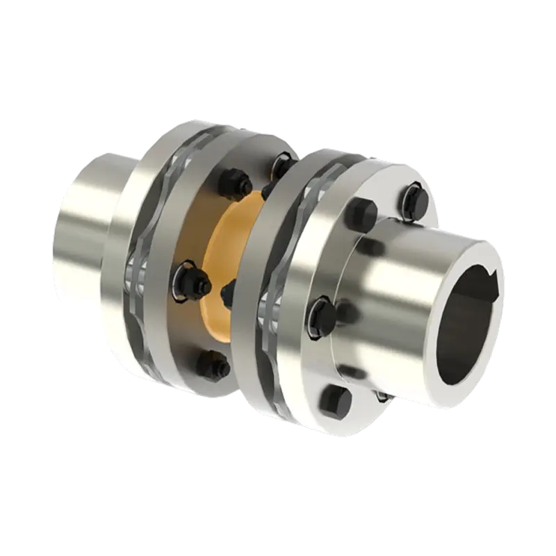
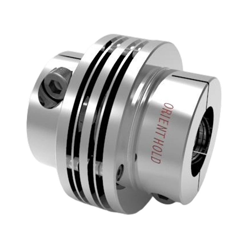
During a routine vibration survey on a high-speed compressor train, engineers found a 4.5 mm/s velocity spike at the mo...
READ MORE
High-Performance Diaphragm Couplings for Accurate and Reliable Power Transmission
Admin 2026-09-07Content
- 1 Understanding the Role of a Diaphragm Coupling
- 2 Structural Design of the JMI Diaphragm Coupling
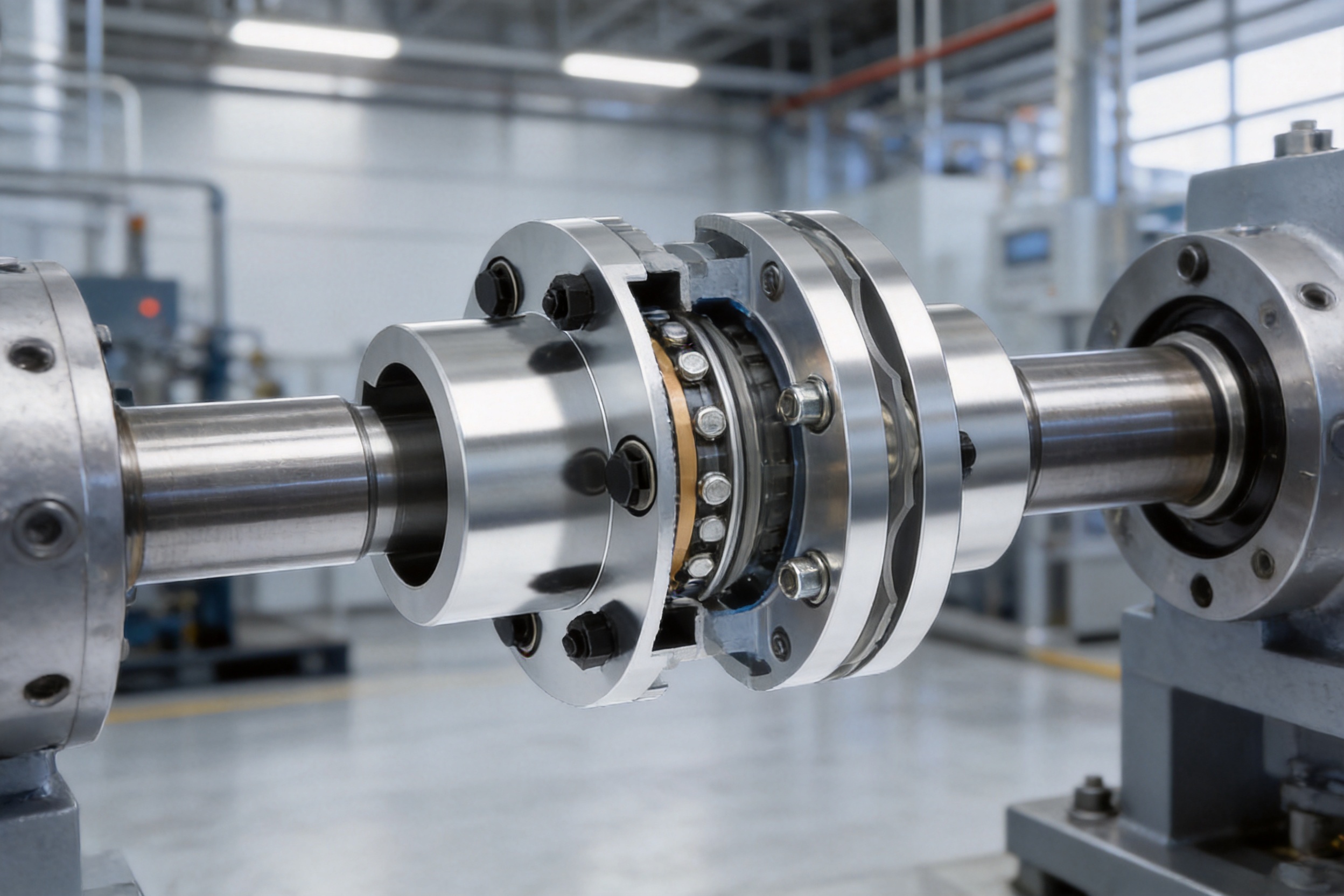
- 3 How Metal Diaphragms Accommodate Misalignment
- 4 Advantages Over Traditional Gear Couplings
- 5 Advantages Over Elastomeric and Pin Couplings
- 6 Key Product Benefits
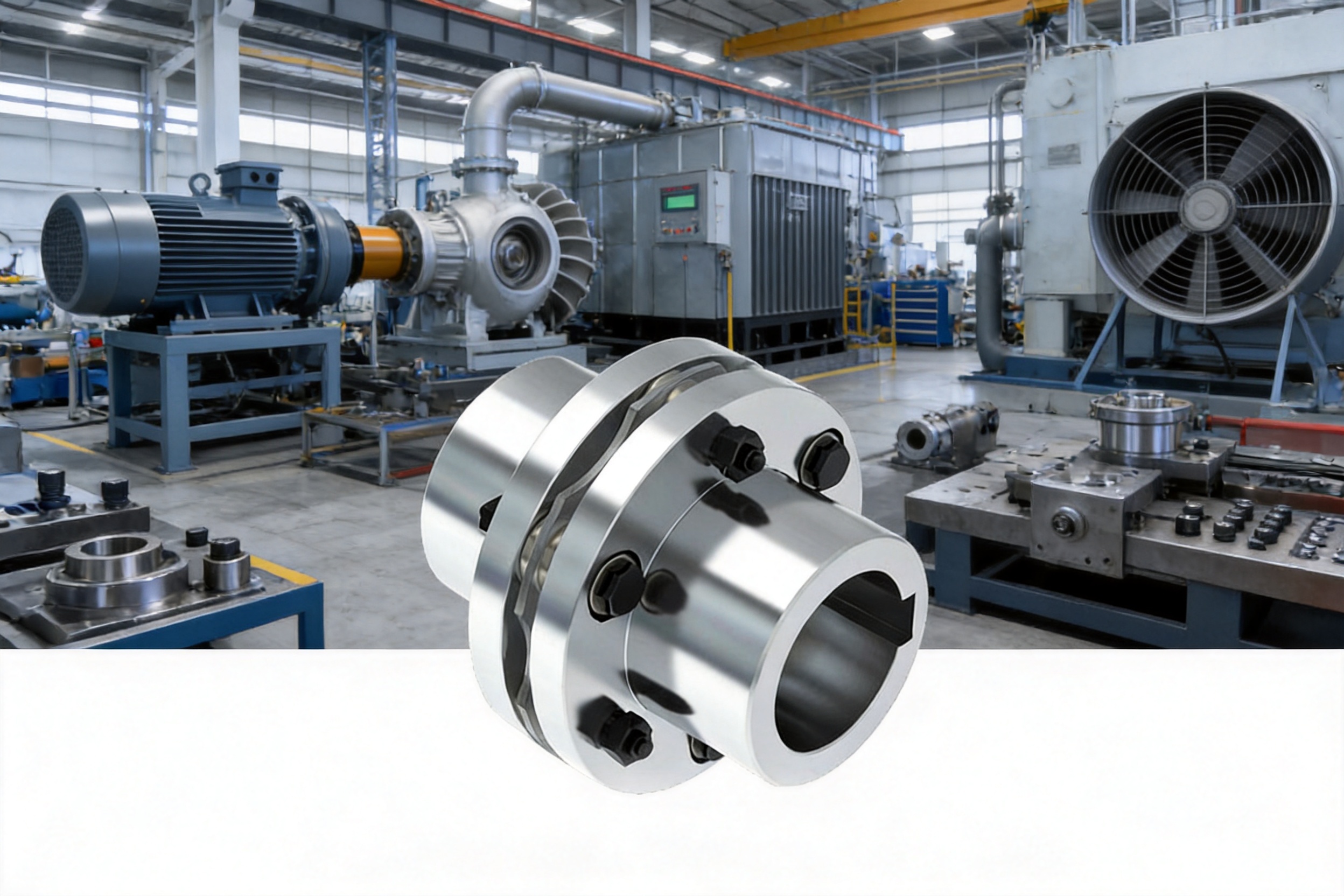
- 7 Applications in Industrial Equipment
- 8 Manufacturing Process and Engineering Control
- 9 Comparison of Coupling Types
- 10 Installation Recommendations
- 11 Maintenance and Service Practices
- 12 Customization and Technical Support
- 13 Why Manufacturing Capability Matters
- 14 Selection Checklist for Buyers
- 15 Safety and Reliability Considerations
- 16 Q&A
- 16.1 What is a diaphragm coupling?
- 16.2 What makes the JMI diaphragm coupling different from a gear coupling?
- 16.3 Does the coupling require lubrication?
- 16.4 Can the coupling correct poor shaft alignment?
- 16.5 Where is this coupling commonly used?
- 16.6 Why is the counterbored bore useful?
- 16.7 Is a diaphragm coupling suitable for high-speed operation?
- 16.8 How does the coupling protect bearings?
- 16.9 How does a diaphragm coupling compare with an elastomeric coupling?
- 16.10 Can the coupling be customized?
- 16.11 What information should be provided for a quotation?
- 16.12 What maintenance does the coupling require?
- 16.13 Why should customers work with an integrated manufacturer?
- 17 Conclusion
- 18 References
- 19 Product: JMI Diaphragm (Disc) Coupling
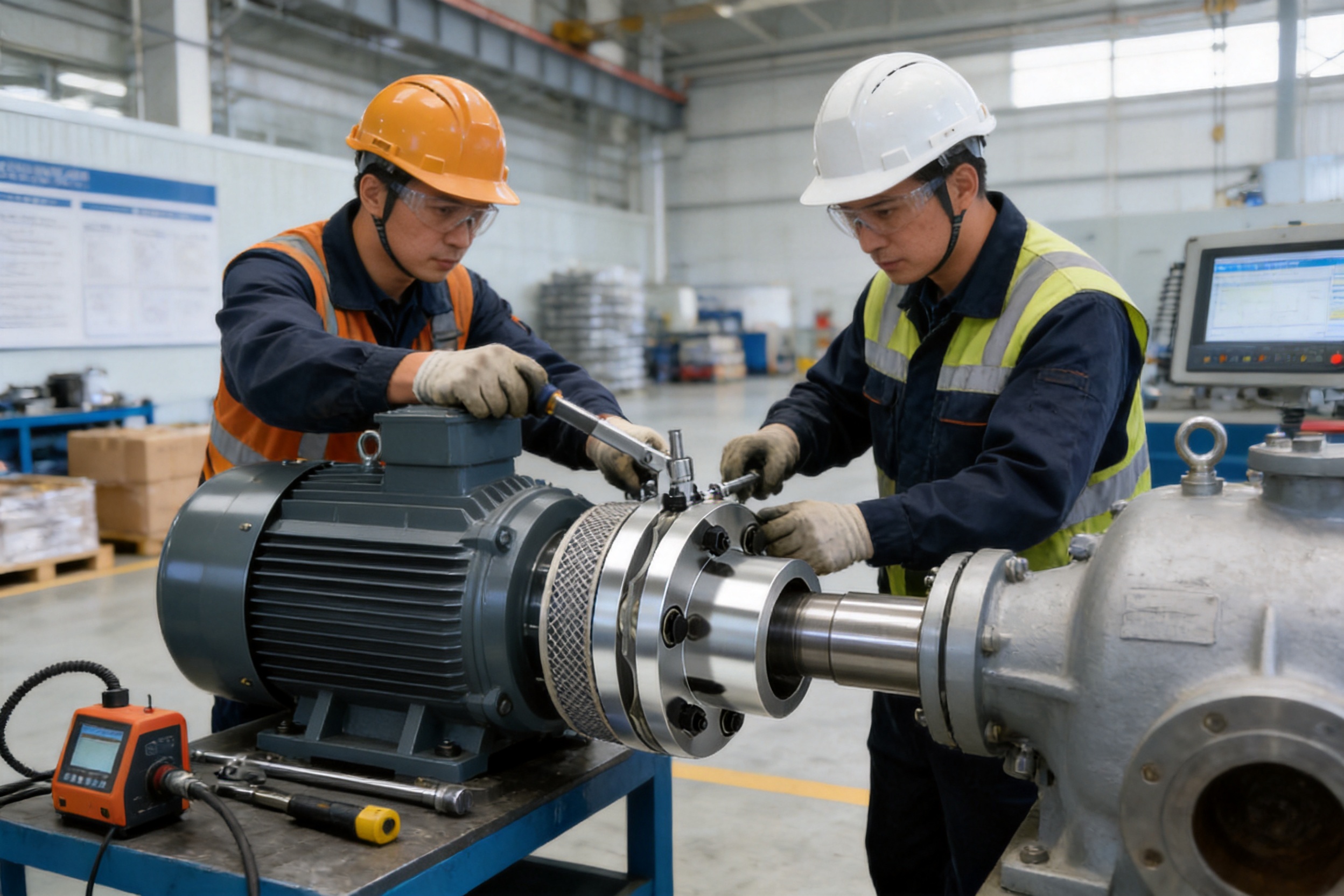
Modern industrial machinery requires a power transmission component that can transfer torque accurately while accommodating the unavoidable misalignment between connected shafts. Fans, pumps, compressors, power generation equipment, and other medium- to high-speed systems are exposed to thermal expansion, installation tolerances, shaft deflection, vibration, and changing operating loads. If these conditions are not properly managed, excessive forces can be transferred to bearings, shaft ends, seals, and connected equipment. Over time, this may lead to vibration, premature wear, unplanned maintenance, and reduced operating efficiency.
The JMI diaphragm coupling is designed to address these challenges through a compact single-section structure and a metal diaphragm assembly that combines torque transmission capability with controlled flexibility. Rather than relying on sliding teeth, lubricated gear engagement, or elastomeric deformation, the coupling uses carefully arranged stainless steel diaphragm packs as its flexible elements. These diaphragms transmit torque through high-strength bolted connections while compensating for axial, radial, and angular misalignment through elastic deformation.
This operating principle gives the diaphragm coupling a number of important advantages for precision machinery. It supports stable transmission, generates comparatively low reaction forces during misalignment compensation, does not require routine lubrication, and is suitable for applications where cleanliness, speed, and operational accuracy are important. Its counterbored bore configuration also contributes to secure shaft attachment and more efficient installation.
Supported by advanced design capability, modern production equipment, comprehensive inspection methods, and a strict quality supervision system, the manufacturer provides coupling solutions for transportation, metallurgy, chemical engineering, mining, construction, hoisting, power generation, and related industries. The combination of product engineering and manufacturing discipline allows the coupling to be adapted to different shaft arrangements, operating environments, and customer requirements.
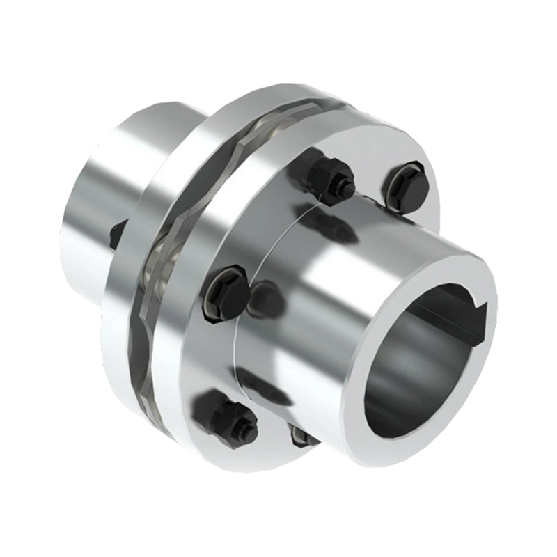
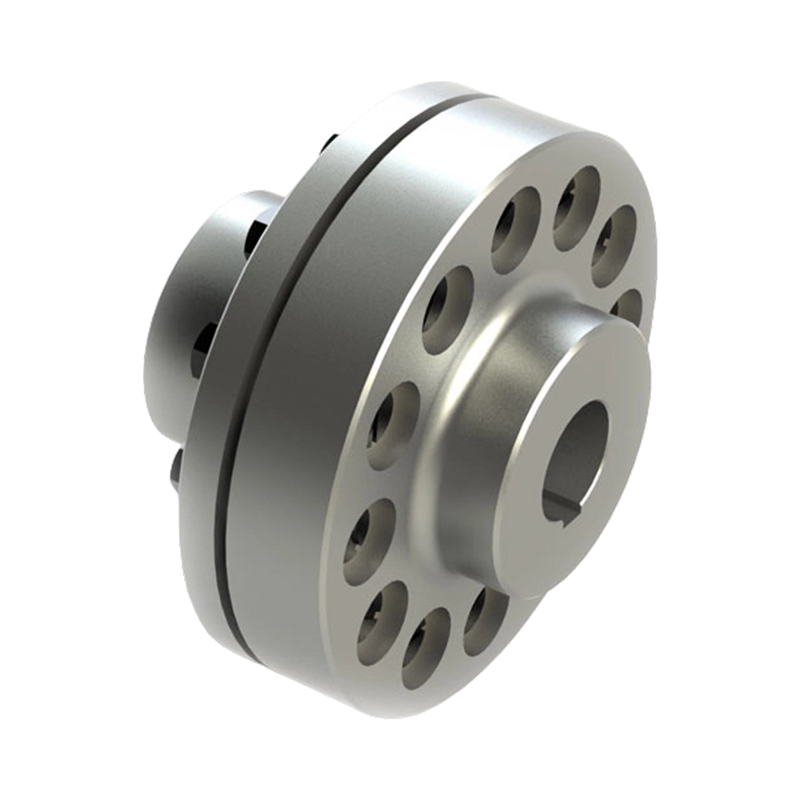
JMI Diaphragm (Disc) Coupling
Understanding the Role of a Diaphragm Coupling
A coupling connects two shafts so that torque can be transmitted from a driving machine to a driven machine. In a typical industrial installation, the driver may be an electric motor, turbine, engine, or other prime mover, while the driven equipment may be a pump, fan, compressor, generator, gearbox, or process machine. Although the shafts are intended to be aligned, perfect alignment is difficult to achieve and even more difficult to maintain during operation.
Misalignment can result from manufacturing tolerances, foundation movement, thermal growth, bearing clearance, shaft deflection, uneven loading, or changes in equipment position. Three basic forms of misalignment are generally considered: angular misalignment, parallel or radial misalignment, and axial displacement. A well-designed flexible coupling allows a controlled degree of movement while continuing to transmit torque.
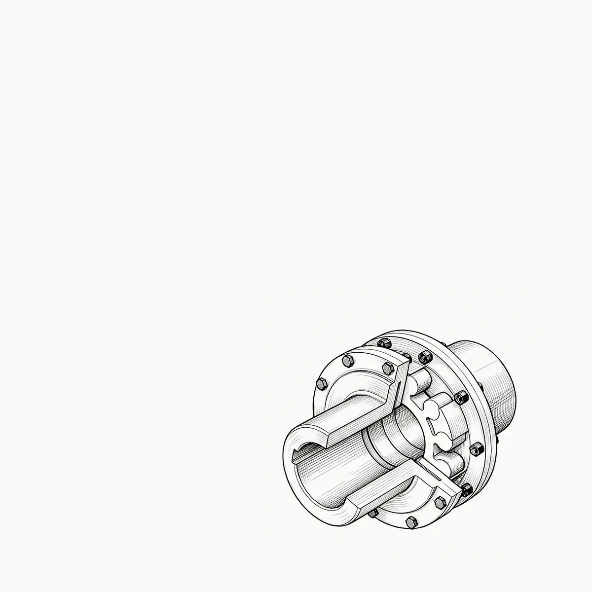
A diaphragm coupling performs this function through thin metal diaphragms. The diaphragms are installed between the coupling flanges and connected by precision bolts. When the shafts rotate, torque is transmitted through the diaphragm pack and the bolted flange connections. When the shafts move relative to one another, the diaphragms flex elastically. This movement allows the coupling to accommodate misalignment without requiring sliding contact between metallic teeth or the compression and shearing of a rubber element.
The diaphragm is therefore both a torque-transmitting and a flexibility-producing component. Its performance depends on material quality, thickness control, bolt-circle accuracy, surface condition, forming precision, and correct assembly. The coupling must be designed so that the diaphragm operates within an appropriate elastic range. When this engineering balance is achieved, the component can provide reliable service over a long operating period.
Structural Design of the JMI Diaphragm Coupling
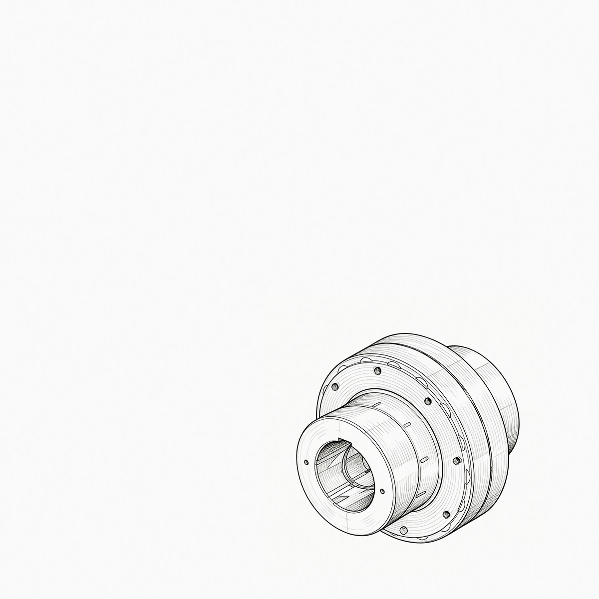
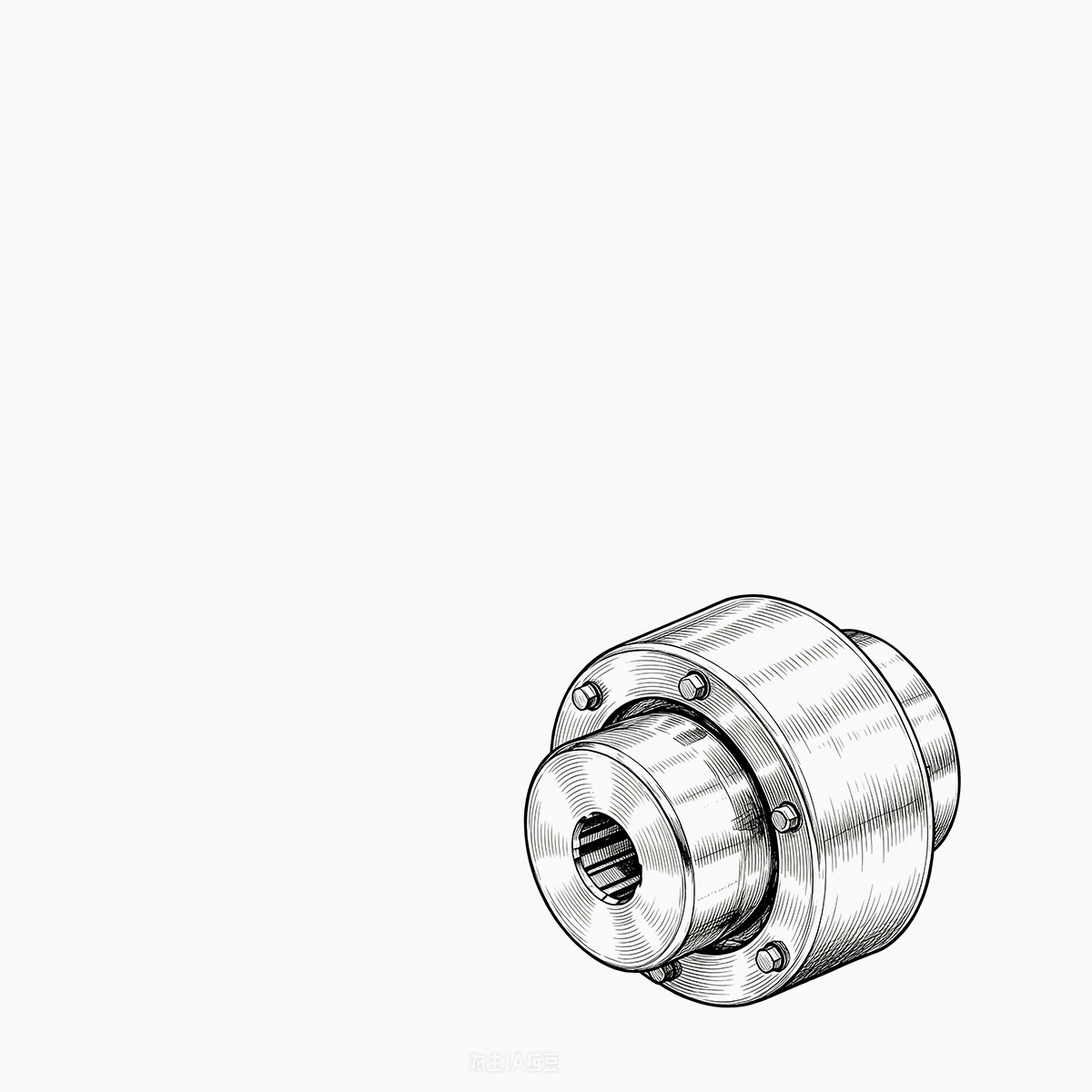
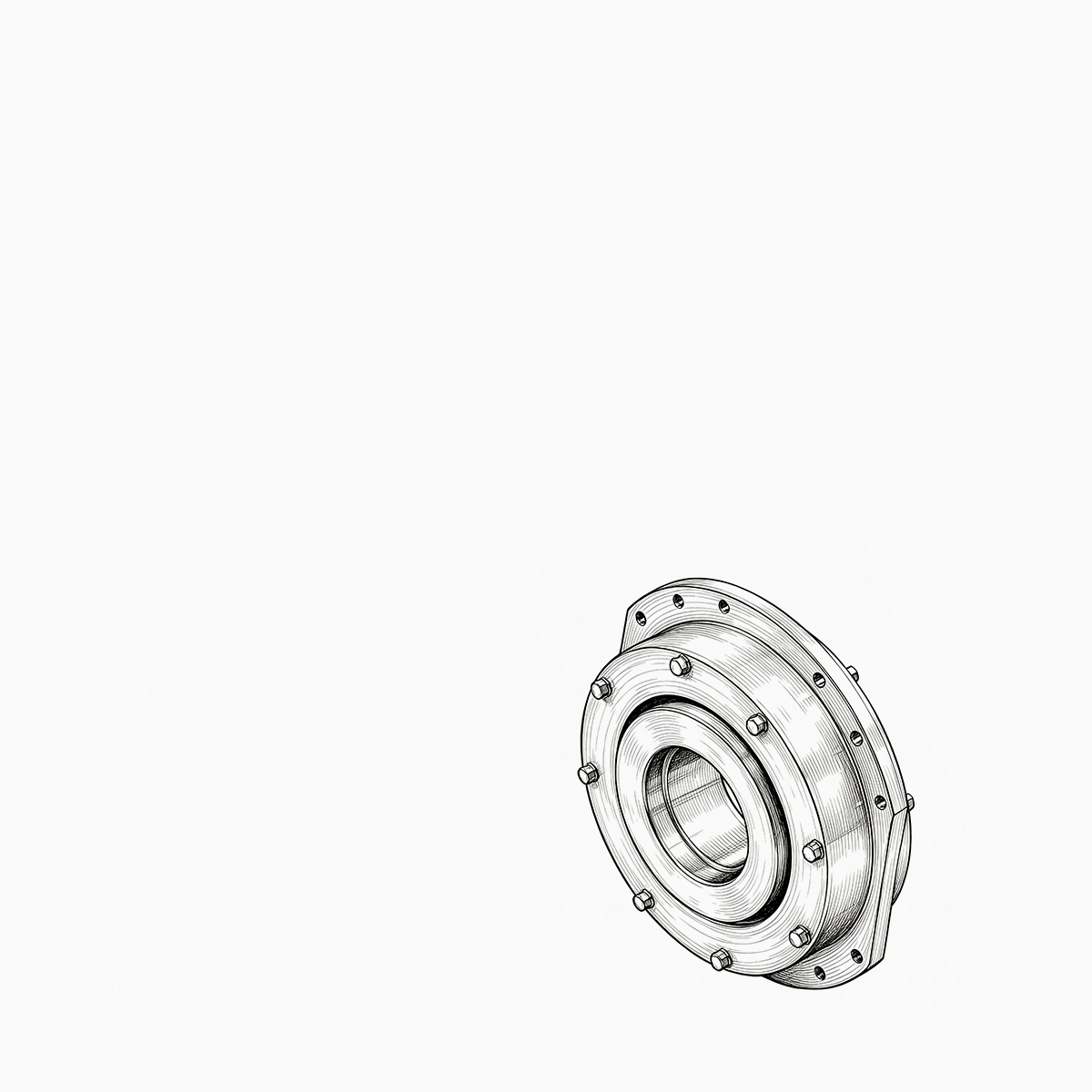
The JMI diaphragm coupling uses a single-section structural layout. This configuration is intended for applications with relatively short transmission distances and high requirements for transmission accuracy and operational stability. Its compact arrangement reduces the overall axial space occupied by the coupling, which can be valuable in machines where the distance between shaft ends is limited.
One half coupling is designed with a counterbored bore. This feature allows the shaft end to be positioned and secured in a practical manner, supporting a stable connection between the coupling and the shaft. The counterbored arrangement can also simplify assembly work because it provides a defined seating area for the shaft or fastening components. In applications where installation access is restricted, a well-designed bore and hub arrangement can reduce assembly difficulties and improve repeatability.
The main flexible element is a metal diaphragm assembly. The diaphragms are generally produced from multiple layers of high-strength stainless steel thin plates. These plates are stacked together and arranged to connect alternately with the driving and driven flanges on the same bolt circle. The layered arrangement helps distribute the transmitted load across the diaphragm pack and supports controlled elastic movement.
High-precision bolts connect the diaphragm packs to the corresponding flanges. The quality of these bolts, the accuracy of the bolt holes, the concentricity of the bolt circle, and the correct tightening sequence all influence final coupling performance. Properly controlled bolted connections help maintain torque transmission capacity and minimize unwanted looseness or uneven loading during operation.
The single-section construction also provides a direct load path between the two connected shafts. By minimizing unnecessary intermediate components, the design can support low backlash and accurate torque transmission. This is particularly useful in rotating machinery where changes in torque, speed, or load must be transferred without substantial delay or hysteresis.
How Metal Diaphragms Accommodate Misalignment
The flexibility of a diaphragm coupling is fundamentally different from the flexibility of an elastomeric coupling. An elastomeric coupling uses a rubber or polymer element that may compress, shear, or deform to accommodate movement. A diaphragm coupling uses the bending and elastic deformation of thin metal plates. The metal diaphragm remains a positive mechanical connection, allowing torque to pass through the coupling without relying on friction between a soft material and a hub.
When angular misalignment occurs, the diaphragm pack bends as the two shaft centerlines form an angle. When radial misalignment occurs, the diaphragm undergoes a controlled combination of bending and displacement. During axial movement, the diaphragm flexes in a manner that permits the connected shafts to move closer together or farther apart within the designed operating range.
Each form of misalignment creates a corresponding reaction force. The design objective is not to eliminate these forces completely, because every flexible coupling must resist some movement, but to keep them controlled and appropriate for the connected equipment. The JMI diaphragm coupling is engineered to compensate for misalignment while generating relatively low reaction forces compared with many traditional gear coupling arrangements.
Lower reaction forces can be beneficial because they reduce the additional loads imposed on bearings and shaft ends. Bearing loads influence bearing temperature, service life, lubrication requirements, and vibration behavior. Shaft-end loads can influence fatigue life, seal performance, and the stability of connected components. By managing these forces through elastic diaphragm movement, the coupling can contribute to the durability of the complete transmission system.
Misalignment compensation does not remove the need for correct installation. A flexible coupling is not intended to correct unlimited alignment errors. Excessive misalignment can increase diaphragm stress, raise bearing loads, and shorten service life. The coupling should therefore be installed with accurate shaft alignment, and the allowable axial, radial, and angular values should be established according to the final design and operating conditions.
Advantages Over Traditional Gear Couplings
Gear couplings are widely used in heavy-duty transmission systems because their toothed hubs can transmit substantial torque within a relatively compact envelope. However, they commonly require lubrication to reduce tooth wear and manage friction. Their maintenance condition depends on the quality, quantity, and retention of the lubricant. In demanding environments, lubricant leakage, contamination, or insufficient maintenance can affect service reliability.
A diaphragm coupling does not use meshing gear teeth and does not depend on sliding tooth contact. Its metal diaphragm assembly transfers torque through a positive bolted structure. As a result, the coupling does not require routine gear-tooth lubrication. This can simplify maintenance planning and reduce the possibility of lubricant-related contamination around nearby equipment.
The absence of sliding tooth engagement can also contribute to stable operation at medium and high speeds. Gear tooth clearance, tooth wear, lubricant condition, and backlash may influence dynamic behavior. A diaphragm coupling, when correctly designed and balanced, can provide a more direct mechanical connection with low backlash and consistent torque transmission characteristics.
Another important distinction is the reaction force associated with misalignment. Gear couplings can generate significant forces when their teeth operate at an angle or when the connected shafts move laterally. The diaphragm coupling compensates through the elastic bending of thin metal plates. This can help reduce the load transferred to bearings and shaft ends, especially in precision rotating machinery.
Diaphragm couplings also avoid the periodic replacement requirements associated with many rubber or polymer flexible elements. Elastomeric components can be affected by temperature, oil, ozone, ultraviolet exposure, chemical contact, aging, and repeated cyclic loading. The metal diaphragms used in the JMI design are intended for environments where a clean, non-lubricated, and mechanically stable flexible element is preferred.
These advantages do not mean that a diaphragm coupling is the universal replacement for every other coupling type. Gear couplings may remain appropriate for some extremely high-torque or long-span applications, while elastomeric couplings may be preferred where strong vibration damping is the primary requirement. The selection should be based on torque, speed, misalignment, environment, axial space, torsional behavior, maintenance objectives, and the requirements of the connected machinery.
Advantages Over Elastomeric and Pin Couplings
Elastomeric pin couplings, elastic sleeve pin couplings, plum elastic couplings, tire couplings, and similar products use polymer or rubber components to provide flexibility. These designs can offer useful vibration isolation and shock absorption. They are often selected for general industrial drives where moderate speed, convenient installation, and damping are more important than extremely precise torque transmission.
The JMI diaphragm coupling is better suited to applications that prioritize torsional accuracy, low backlash, high-speed stability, and predictable performance over time. Metal diaphragms do not creep in the same manner as polymer elements. They also maintain their mechanical characteristics across a broader range of operating conditions, provided that the coupling is correctly selected and not exposed to loads beyond its design limits.
A diaphragm coupling can be advantageous in equipment where torsional oscillation must be controlled through accurate transmission rather than through strong soft-element damping. For example, a compressor or generator train may require a coupling that passes torque with minimal lost motion and maintains stable alignment behavior at operating speed.
At the same time, elastomeric couplings can have an advantage where impact loads and vibration isolation are dominant concerns. A metal diaphragm does not provide the same level of soft damping as a rubber tire or elastomeric insert. The correct product therefore depends on the machine’s dynamic characteristics. The strength of the JMI design lies in its precision, cleanliness, compactness, and controlled metal flexibility.
Compared with some pin-based couplings, the diaphragm construction can provide a more consistent connection because it does not depend on a group of polymer sleeves or flexible pins to carry the operating load. The metal diaphragm pack distributes load around the bolt circle and can support stable performance when the bolts, diaphragms, and flange interfaces are accurately manufactured.
Key Product Benefits
Accurate Torque Transmission
The diaphragm coupling provides a direct mechanical connection between the driving and driven shafts. Its positive bolted diaphragm arrangement supports accurate transfer of rotational movement and torque. The absence of sliding gear teeth or soft polymer inserts helps limit lost motion, making the coupling suitable for drives where transmission accuracy is important.
Controlled Misalignment Compensation
Through elastic deformation, the metal diaphragms accommodate axial, radial, and angular misalignment. This flexibility supports reliable operation when equipment experiences thermal expansion, shaft deflection, or minor installation variation. The coupling must still be installed carefully, but its flexible structure helps prevent every small movement from becoming a damaging rigid load.
Low Maintenance Requirement
The coupling does not rely on gear-tooth lubrication or replaceable rubber elements for its basic operation. This can reduce routine maintenance tasks and simplify inspection schedules. Operators should still check bolt condition, alignment, coupling condition, and signs of abnormal vibration, but the absence of lubricant management is a practical advantage.
Compact Single-Section Structure
The single-section layout is suitable for installations with a relatively short distance between shaft ends. Its compact design helps save axial space and can make it easier to integrate the coupling into fans, pumps, compressors, generators, and other rotating assemblies.
High-Speed Suitability
Diaphragm couplings are commonly selected for medium- and high-speed systems because their balanced metal construction and low-backlash behavior can support stable rotation. Final speed suitability depends on coupling size, balance grade, shaft arrangement, operating temperature, and the dynamic characteristics of the connected equipment.
Reduced Bearing and Shaft-End Loading
Because the diaphragm compensates for misalignment through elastic bending, the coupling can generate lower reaction forces than some traditional designs. This helps reduce unnecessary loads on bearings and shaft ends. Lower secondary loading may support improved bearing life, reduced vibration, and more stable operation of seals and connected machinery.
Clean Operation
The absence of coupling grease makes the design useful in installations where cleanliness is important. This may include power generation equipment, process machinery, high-speed fans, and equipment positioned near sensitive components. A clean coupling arrangement can also make visual inspection and maintenance work more straightforward.
Applications in Industrial Equipment
Fans and Blowers
Fans and blowers often operate at substantial rotational speeds and may experience thermal movement or shaft deflection during continuous service. A compact diaphragm coupling can transmit torque from the motor to the fan shaft while accommodating controlled misalignment. Its low-maintenance construction is especially useful in installations where access to the coupling is limited.
Pumps
Pump systems can be sensitive to bearing loads and alignment changes. Temperature variation, pipe strain, foundation movement, and maintenance activity may affect shaft alignment. A flexible diaphragm coupling helps protect the drive and pump shafts from becoming a completely rigid system while maintaining accurate power transmission.
Compressors
Compressors frequently operate under demanding conditions involving high rotational speed, continuous duty, and changing process loads. The coupling must maintain stable torque transmission while limiting unnecessary forces on bearings and shafts. The diaphragm design is appropriate for compressor drives where high accuracy and operational stability are required.
Power Generation Equipment
Generators, auxiliary turbines, excitation systems, and related power equipment require dependable rotating connections. Unplanned coupling problems can lead to significant production interruptions. A metal diaphragm coupling can support the reliability objectives of these systems through its compact construction, positive torque transmission, and reduced maintenance requirements.
Metallurgical and Mining Equipment
Metallurgical and mining machinery may be exposed to dust, vibration, changing loads, and harsh working conditions. The coupling selection must account for environmental contamination, shock loading, speed, and maintenance access. Where the application requires a clean metal flexible element and accurate transmission, the diaphragm coupling can provide a valuable alternative to lubricated gear couplings and polymer-based designs.
Construction and Hoisting Machinery
Construction and hoisting equipment can experience frequent starts, stops, load changes, and movement of the supporting structure. The final coupling selection should consider peak torque and shock loads carefully. In suitable applications, the JMI coupling can be used where compactness, controlled misalignment compensation, and reliable shaft connection are required.
Transportation and Process Systems
Industrial transportation systems, process lines, and auxiliary drive units often require reliable power transmission within limited installation spaces. The coupling can be integrated into a variety of shaft arrangements and customized according to equipment dimensions, torque requirements, bore sizes, and connection conditions.
Manufacturing Process and Engineering Control
The performance of a diaphragm coupling is determined not only by its general design but also by the consistency of the manufacturing process. Thin metal diaphragms, flanges, hubs, bolts, and bore surfaces must work together as a balanced mechanical system. Small dimensional errors can influence alignment, stress distribution, vibration, and service life.
The manufacturer integrates product design, production, inspection, and service. This integrated structure allows technical requirements to be considered from the beginning of the project rather than being addressed only after production. Customer operating information can be reviewed by engineering personnel, translated into a coupling configuration, and then checked against manufacturing and testing capabilities.
Engineering and Application Review
Before production, the application should be reviewed according to the driver and driven machine, nominal and peak torque, rotational speed, operating hours, shaft diameter, shaft-end distance, misalignment, ambient temperature, installation conditions, and maintenance objectives. This information supports the selection of a suitable coupling size and configuration.
For specialized equipment, the manufacturer can evaluate the required bore arrangement, hub length, bolt-circle dimensions, keyway, flange connection, surface treatment, balance requirements, and installation limitations. A careful application review helps avoid selecting a coupling solely according to nominal torque while overlooking speed, transient loading, or alignment conditions.
Material and Component Preparation
The diaphragms require high-strength thin metal plates with consistent mechanical properties and surface quality. Stainless steel is commonly used for its combination of strength, corrosion resistance, fatigue performance, and dimensional stability. Material preparation should include inspection of thickness, flatness, surface condition, and traceability where required.
Hubs and flanges must be produced from suitable engineering materials with adequate strength and machinability. Their geometry must support the transmission of torque and the controlled mounting of the diaphragm packs. Bolts and fastening components should be selected to withstand the applied loads while maintaining secure clamping during operation.
Precision Machining
Machining accuracy is essential for the bore, hub, flange faces, bolt holes, counterbore, and locating surfaces. The counterbored bore must provide a reliable fit and seating arrangement for the shaft connection. Concentricity between the bore and the coupling’s rotational centerline is particularly important because eccentricity can increase vibration at operating speed.
Flange and bolt-circle machining must be controlled so that the diaphragm pack is mounted evenly. Uneven hole positioning or poor face alignment can cause local stress concentration and imbalance. Precision equipment and appropriate process inspection help maintain the dimensional relationship between the coupling components.
Diaphragm Pack Assembly
The diaphragm plates are assembled into packs according to the design arrangement. The plates must be aligned correctly, free from damage, and connected to the driving and driven flanges in the specified sequence. The alternating connection pattern allows the diaphragm pack to transmit torque and flex in a controlled manner.
Bolts are installed using an appropriate tightening sequence and controlled tightening method. Consistent bolt preload helps distribute load evenly around the bolt circle. If fastening is uneven, individual bolts or areas of the diaphragm may carry more than their intended share of the load. Assembly records and inspection procedures can help ensure repeatability between production units.
Balancing and Dynamic Inspection
Medium- and high-speed couplings require attention to balance. The coupling’s rotating mass must be distributed as evenly as possible around the centerline. Manufacturing controls should minimize eccentricity, irregular material removal, and assembly variation. Depending on the application, dynamic balance inspection may be included to verify suitability for the required operating speed.
Dynamic inspection can help identify imbalance that might not be apparent during a simple visual examination. The objective is to reduce vibration, protect bearings, and support stable operation after the coupling is installed in the complete machine.
Quality Inspection and Testing
A complete quality supervision system should cover incoming materials, machining, component inspection, assembly, final dimensions, surface condition, fastening, and packaging. The manufacturer maintains comprehensive inspection and testing equipment to support these controls. Testing procedures may be arranged according to product type, customer requirements, and applicable national or industrial standards.
Inspection of the finished coupling may include bore dimensions, keyway dimensions, flange runout, bolt-circle accuracy, concentricity, axial dimensions, surface defects, assembly condition, and identification marking. Where required, operational or balance testing can provide additional confirmation of product performance.
The value of a quality system is not limited to identifying defective products. It also creates process feedback. If inspection results show repeated variation in a machining or assembly operation, corrective action can be taken before the issue affects larger production quantities. This approach supports consistent product quality and more reliable delivery.
Comparison of Coupling Types
Industrial users often compare diaphragm couplings with gear, elastomeric pin, sleeve pin, cross universal, plum, tire, and drum couplings. Each design has its own application range. The following comparison presents general characteristics rather than replacing a project-specific technical evaluation.
| Coupling type | Primary flexible element | Typical strengths | Important selection considerations |
|---|---|---|---|
| Diaphragm coupling | Metal diaphragm pack | Accurate torque transmission, low backlash, compact design, no routine lubrication, suitability for medium- and high-speed drives | Requires proper alignment, careful bolt assembly, and attention to diaphragm stress and balance |
| Gear coupling | Meshing metallic gear teeth | High torque capacity and broad industrial use | Usually requires lubrication; tooth wear, sealing, backlash, and maintenance must be considered |
| Elastomeric pin coupling | Polymer pins or sleeves | Simple construction and useful vibration absorption | Polymer aging, temperature limits, chemical compatibility, and replacement requirements |
| Plum elastic coupling | Elastomeric spider | Compact form and convenient general-purpose installation | Spider hardness, temperature, oil exposure, and torsional damping affect performance |
| Tire coupling | Rubber tire element | Strong vibration isolation and shock absorption | Radial installation space, rubber aging, and speed limitations may be important |
| Drum coupling | Application-specific metallic or flexible assembly | Often used in hoisting and heavy-duty equipment | Brake drum geometry, load cycles, space, and hoisting safety requirements require detailed review |
| Cross universal coupling | Cross and bearing assembly | Accommodates angular shaft arrangements and larger operating angles | Bearing lubrication, wear, operating angle, and maintenance access must be considered |
The comparison shows why product selection should be based on the complete machine rather than on torque rating alone. A customer seeking low maintenance and accurate high-speed transmission may prefer a diaphragm coupling. A customer needing high torsional damping may choose an elastomeric design. A heavy hoisting installation may require a drum or gear coupling with specific load-handling characteristics.
Installation Recommendations
Correct installation is essential for achieving the intended performance of the diaphragm coupling. Before installation, the shaft ends, bores, keyways, hubs, flange faces, bolts, and diaphragm packs should be inspected. Components should be clean and free from burrs, corrosion, oil contamination, or impact damage.
The shaft alignment should be checked in the axial, radial, and angular directions. The coupling can accommodate a controlled amount of misalignment, but it should not be used as a substitute for proper alignment. Excessive initial misalignment increases diaphragm stress and may create unnecessary forces on the connected bearings.
The counterbored bore and shaft-end arrangement should be assembled according to the approved drawing or installation instructions. The shaft should reach the intended seating position without forcing the coupling into place. If a key is used, it must be correctly fitted and should not create interference that prevents proper hub seating.
Bolts should be inspected for correct grade, thread condition, length, and cleanliness. The diaphragm and flange connections should be tightened in a controlled crosswise sequence. Applying the specified tightening torque consistently is important because unequal bolt preload can produce uneven stress distribution and affect balance.
After assembly, the coupling should be rotated by hand where practical to confirm that there is no interference. Guards should be installed before operation. During commissioning, operators should observe vibration, noise, temperature, and any abnormal movement. A gradual start-up can help identify installation problems before the machine reaches full operating conditions.
Maintenance and Service Practices
Although the diaphragm coupling does not require gear lubrication, it still benefits from a planned inspection program. Maintenance personnel should check the coupling at intervals appropriate to the equipment’s speed, duty cycle, environment, and criticality.
Visual inspection should look for damaged or distorted diaphragm plates, loose or missing bolts, corrosion, contact marks, abnormal fretting, shaft movement, and changes in the position of the coupling relative to the connected equipment. Any unusual noise or vibration should be investigated rather than ignored.
Bolt condition is especially important. A loose connection can change load distribution around the diaphragm pack and increase stress in adjacent components. If a bolt must be replaced, the replacement should match the approved specification. Improvised fasteners or uncontrolled tightening can compromise coupling performance.
Alignment should be rechecked after major maintenance, bearing replacement, foundation work, piping changes, or any event that may have moved the driver or driven machine. Thermal growth should also be considered where the equipment operates at a significantly different temperature from the alignment condition.
Diaphragm packs should not be bent, hammered, clamped improperly, or used as lifting points. Damage introduced during installation may not be visible immediately but can reduce fatigue life during operation. If the coupling experiences an overload, collision, severe vibration event, or unexpected shutdown, it should be inspected before the machine is returned to service.
Customization and Technical Support
Industrial coupling requirements are rarely identical from one machine to another. Shaft diameters, shaft-end distances, keyway forms, mounting spaces, torque values, speeds, ambient conditions, and connection methods vary across industries. A manufacturer with design and production capability can adapt the coupling to these requirements more effectively than a supplier offering only fixed standard configurations.
Customization may involve bore dimensions, counterbore depth, hub length, bolt-circle arrangement, flange dimensions, diaphragm pack design, surface treatment, balance requirements, or special mounting features. Any modification should be evaluated by qualified engineering personnel because changes to the diaphragm or hub geometry can influence stress, speed capability, and misalignment performance.
The manufacturer’s technical service can support customers from the initial product inquiry through installation and after-sales maintenance. Pre-sales consultation may help determine the appropriate coupling type and size. During production, technical communication can confirm drawings, dimensions, materials, and inspection requirements. After delivery, service support can assist with installation questions, replacement parts, maintenance guidance, and future customization.
Flexible logistics and payment options can also help customers coordinate coupling procurement with larger equipment projects. Reliable packaging and identification are important because couplings may be shipped as part of international machinery orders and may not be installed immediately after delivery. Clear documentation supports proper storage, identification, and installation.
Why Manufacturing Capability Matters
A coupling is a relatively compact component, but its influence on the reliability of a complete machine can be substantial. A dimensional error in the bore, an uneven flange face, an incorrectly assembled diaphragm, or an improperly tightened bolt can produce vibration and stress throughout the drive train. For this reason, manufacturing capability must include more than basic machining.
Orienthold Machinery integrates design, production, inspection, and service within one organization. Its production experience covers couplings and papermaking machinery, allowing the company to work with equipment used in transportation, metallurgy, chemical engineering, mining, construction, hoisting, and other industrial fields.
Advanced equipment supports the production of hubs, flanges, bores, counterbores, bolt holes, and other precision features. Comprehensive testing equipment supports dimensional verification and product evaluation. A strict quality supervision system helps ensure that products comply with applicable national standards and meet the technical expectations of industrial customers.
The company’s medium-sized structure can also support practical communication and flexible response. Large industrial projects often require clarification of drawings, modification of dimensions, coordination of delivery schedules, and adaptation to a customer’s existing equipment. A responsive technical and production team can reduce communication delays and help maintain project continuity.
Another strength is the company’s understanding of complete industrial service. Product supply is supported by pre-sales consultation, customization, logistics coordination, payment flexibility, and maintenance assistance. This one-stop approach is valuable for customers who need more than a standard catalog component and prefer to work with a supplier capable of supporting the entire procurement process.
Selection Checklist for Buyers
Before ordering a diaphragm coupling, buyers should prepare accurate information about the application. The following questions can help establish a suitable technical basis:
What is the driver type and the driven machine type?
What are the normal, maximum, and transient torque values?
What is the operating speed and are there speed changes during operation?
What are the shaft diameters, keyway dimensions, shaft-end distances, and available installation space?
What levels of axial, radial, and angular misalignment may occur during operation?
Will the equipment experience thermal expansion, foundation movement, vibration, shock loading, or frequent starts and stops?
What are the ambient temperature, humidity, dust, chemical exposure, and cleanliness requirements?
Is routine lubrication difficult or undesirable at the installation location?
Are there special requirements for balance, noise, vibration, corrosion resistance, or inspection documentation?
Will the coupling be installed in a new machine or used as a replacement for an existing coupling?
Providing complete information allows the supplier to recommend a more appropriate configuration. It also reduces the risk of selecting a coupling based only on nominal power while overlooking peak loads, dynamic behavior, or installation constraints.
Safety and Reliability Considerations
Rotating couplings can present serious hazards if they are operated without proper guarding. The diaphragm coupling should always be enclosed by a suitable guard that prevents contact with rotating parts and protects personnel from loose components in the event of a failure.
Installation and maintenance should be performed by qualified personnel using appropriate tools and procedures. The driver should be isolated from its energy source before any work is carried out. The coupling must not be touched while rotating, even if it appears to be operating smoothly.
Reliability depends on both product quality and system conditions. A correctly manufactured coupling may still fail prematurely if it is overloaded, misaligned, incorrectly assembled, exposed to unexpected corrosion, or operated beyond its rated speed. Clear communication between the coupling manufacturer, equipment designer, installer, and end user is therefore essential.
Where the coupling is used in a critical process, customers may consider maintaining inspection records, installation measurements, bolt tightening records, operating vibration trends, and replacement history. This information can support predictive maintenance and help identify changes before they develop into serious failures.
Q&A
What is a diaphragm coupling?
A diaphragm coupling is a flexible shaft coupling that uses thin metal diaphragm packs as its elastic elements. It transmits torque through the diaphragms and bolted flanges while accommodating axial, radial, and angular misalignment through controlled elastic deformation.
What makes the JMI diaphragm coupling different from a gear coupling?
The JMI diaphragm coupling uses metal diaphragms rather than meshing gear teeth. It does not require routine gear lubrication, provides low-backlash torque transmission, and can generate lower reaction forces during misalignment compensation. It is especially suitable for compact, accurate, and medium- to high-speed drive systems.
Does the coupling require lubrication?
The diaphragm assembly itself does not require gear lubrication for normal operation. However, other machine components, such as bearings or connected gearboxes, may have their own lubrication requirements. The complete equipment maintenance program should address those components separately.
Can the coupling correct poor shaft alignment?
The coupling can compensate for a controlled amount of axial, radial, and angular misalignment, but it should not be used to correct poor installation. Excessive misalignment increases diaphragm stress and may reduce service life. Accurate initial alignment remains essential.
Where is this coupling commonly used?
Common applications include fans, pumps, compressors, power generation equipment, and other medium- to high-speed industrial drives. It may also be suitable for machinery used in transportation, metallurgy, chemical engineering, mining, construction, and hoisting when the operating conditions match the coupling’s design characteristics.
Why is the counterbored bore useful?
The counterbored bore provides a practical shaft-end seating and fastening arrangement. It can improve connection stability and make assembly more efficient, particularly where shaft and coupling dimensions must be positioned accurately within limited installation space.
Is a diaphragm coupling suitable for high-speed operation?
Diaphragm couplings are commonly selected for medium- and high-speed systems because of their compact metal construction, low backlash, and potential for stable dynamic behavior. The actual allowable speed depends on the coupling size, balance condition, shaft arrangement, operating temperature, and application requirements.
How does the coupling protect bearings?
When the connected shafts move because of thermal expansion or other operating conditions, the diaphragm flexes to accommodate the movement. This can reduce the reaction forces transferred to bearings and shaft ends compared with some rigid or gear-based arrangements. Correct alignment and proper selection remain necessary.
How does a diaphragm coupling compare with an elastomeric coupling?
A diaphragm coupling generally provides more precise torque transmission, low backlash, and stable metal flexibility. An elastomeric coupling often provides stronger vibration damping and shock absorption. The best choice depends on whether the application prioritizes accuracy and high-speed stability or soft torsional damping.
Can the coupling be customized?
Yes. Depending on the project, customization may include bore size, keyway, hub length, bolt-circle dimensions, flange configuration, diaphragm arrangement, balance requirements, surface treatment, and other installation features. All modifications should be reviewed by the manufacturer’s engineering team.
What information should be provided for a quotation?
Customers should provide driver and driven equipment details, power or torque, speed, shaft diameters, shaft-end distance, keyway information, expected misalignment, operating temperature, environment, duty cycle, installation space, and any balance or documentation requirements.
What maintenance does the coupling require?
Maintenance normally includes visual inspection, bolt inspection, alignment checks, vibration monitoring, and examination for diaphragm damage, corrosion, fretting, or abnormal contact marks. The coupling should also be inspected after overloads, collisions, major maintenance, or unexpected vibration events.
Why should customers work with an integrated manufacturer?
An integrated manufacturer can coordinate engineering, machining, assembly, inspection, testing, packaging, and service. This improves communication and supports customization. It also allows quality information and technical requirements to be followed throughout the production process rather than being divided among unrelated suppliers.
Conclusion
The JMI diaphragm coupling is designed for industrial users who need accurate, stable, and low-maintenance power transmission within a compact single-section structure. Its stainless steel diaphragm packs transmit torque directly while accommodating axial, radial, and angular misalignment through controlled elastic deformation. The counterbored bore supports secure shaft attachment, and the bolted diaphragm arrangement provides a positive connection with low backlash.
Compared with traditional gear couplings, the design avoids meshing teeth and routine lubrication while helping reduce reaction forces on bearings and shaft ends. Compared with many elastomeric or pin couplings, it offers more precise metal-to-metal torque transmission and predictable behavior in medium- and high-speed applications. Its suitability is particularly strong in fans, pumps, compressors, generators, and other rotating systems where operational stability and maintenance efficiency are important.
Product performance is supported by manufacturing discipline. Orienthold Machinery combines design, production, advanced equipment, comprehensive inspection, testing capability, and technical service. Its experience across multiple industrial sectors allows it to respond to standard and customized requirements. By integrating pre-sales consultation, engineering review, production control, flexible logistics, and after-sales support, the company provides more than a single coupling component; it provides a complete industrial transmission solution.
For the best result, the coupling should be selected according to the complete operating profile of the machine. Torque, speed, misalignment, environment, shaft dimensions, thermal movement, dynamic behavior, and maintenance requirements should all be considered. With correct selection, accurate installation, suitable guarding, and regular inspection, a diaphragm coupling can contribute to reliable operation, reduced secondary loading, and longer service life for the entire transmission system.
References
1. Industrial Coupling Design Principles, technical reference material for flexible shaft couplings and power transmission systems.
2. Mechanical Power Transmission Handbook, chapters covering shaft alignment, coupling selection, torque transmission, and rotating equipment reliability.
3. Flexible Couplings for Rotating Machinery, engineering guidance on diaphragm, gear, elastomeric, pin, tire, and universal couplings.
4. Industrial Machinery Maintenance Practice, recommendations for coupling installation, bolt inspection, vibration monitoring, and alignment control.
5. Metal Fatigue and Elastic Deformation in Mechanical Components, reference material concerning thin plate flexibility, cyclic loading, and fatigue-conscious design.
6. Quality Control in Precision Machinery Manufacturing, guidance on machining accuracy, dimensional inspection, assembly verification, and dynamic balance testing.
Product: JMI Diaphragm (Disc) Coupling
PREV: JMII Double-Diaphragm Coupling: Precision Torque Transmission for Demanding Industrial SystemsNEXT: No next article
Be the First to Know
For exclusive deals and latest offers, sign up by entering your email address below.
Related products
News
-
-
China's coupling industry is at a critical historical juncture of transformation from scale expansion to quality and eff...
READ MORE -
Industrial Couplings: The Definitive Technical Encyclopedia – Classification, Sizing, Failure Prevention, and Lifecycle...
READ MORE -
A maintenance engineer pulls a failed coupling from a pump drive. The elastomer sleeves are cracked, the pin bolts are ...
READ MORE -
Rotating Equipment Engineering Why Diaphragm Coupling Wins in High-Speed Turbomachinery A close look at how elastic dia...
READ MORE -
Your compressor train is running at 9,800 rpm when the vibration monitor triggers an alarm. The first component your ma...
READ MORE


ABOUT US
PRODUCTS
INDUSTRIES
CONTACT US
- Phone: +86-18652865511
- Email: sales@ohmach.com
- Address: No.1, Minying Developing Zone, Zhenjiang, Jiangsu, China
Copyright Zhenjiang Orienthold Machinery Co., Ltd. All Rights Reserved.
 Custom Industrial Shaft Coupling Manufacturers