 English
 русский
 Português
 عربى
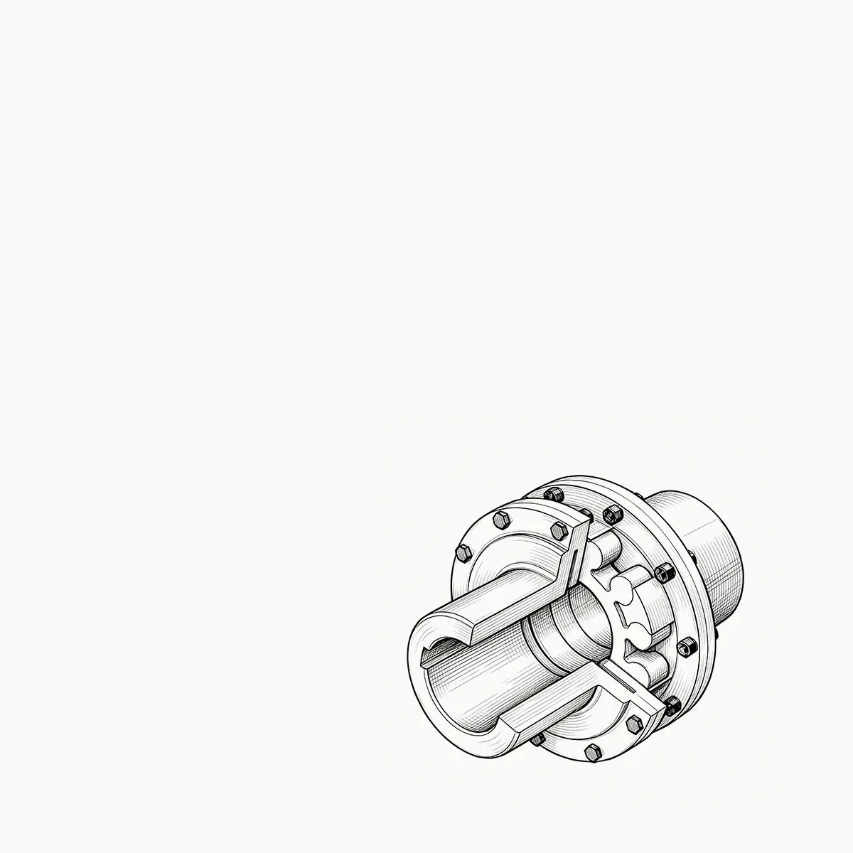
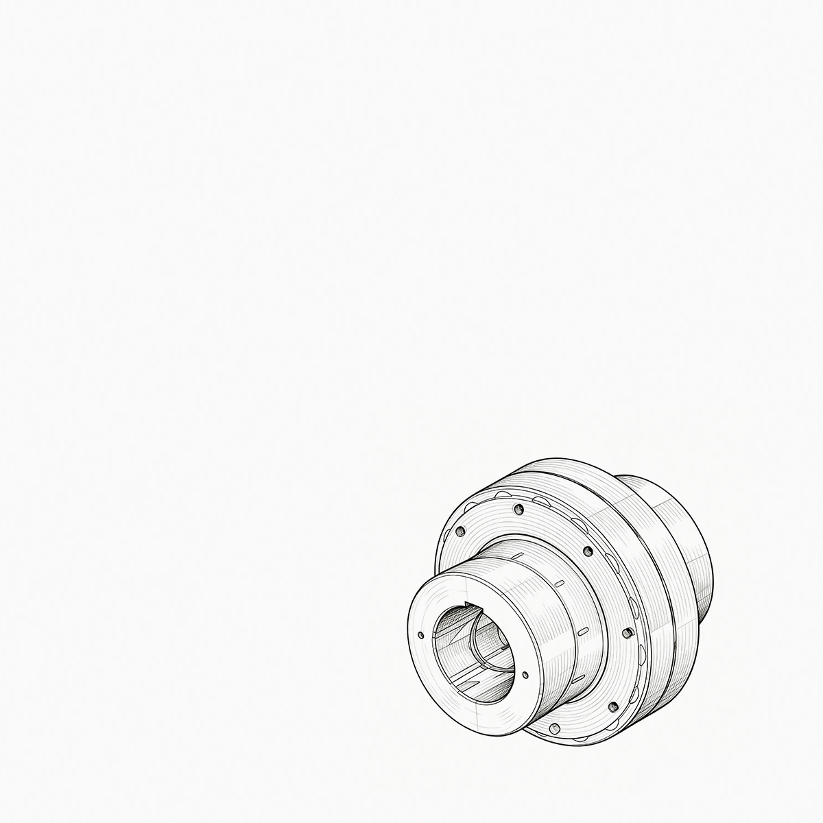
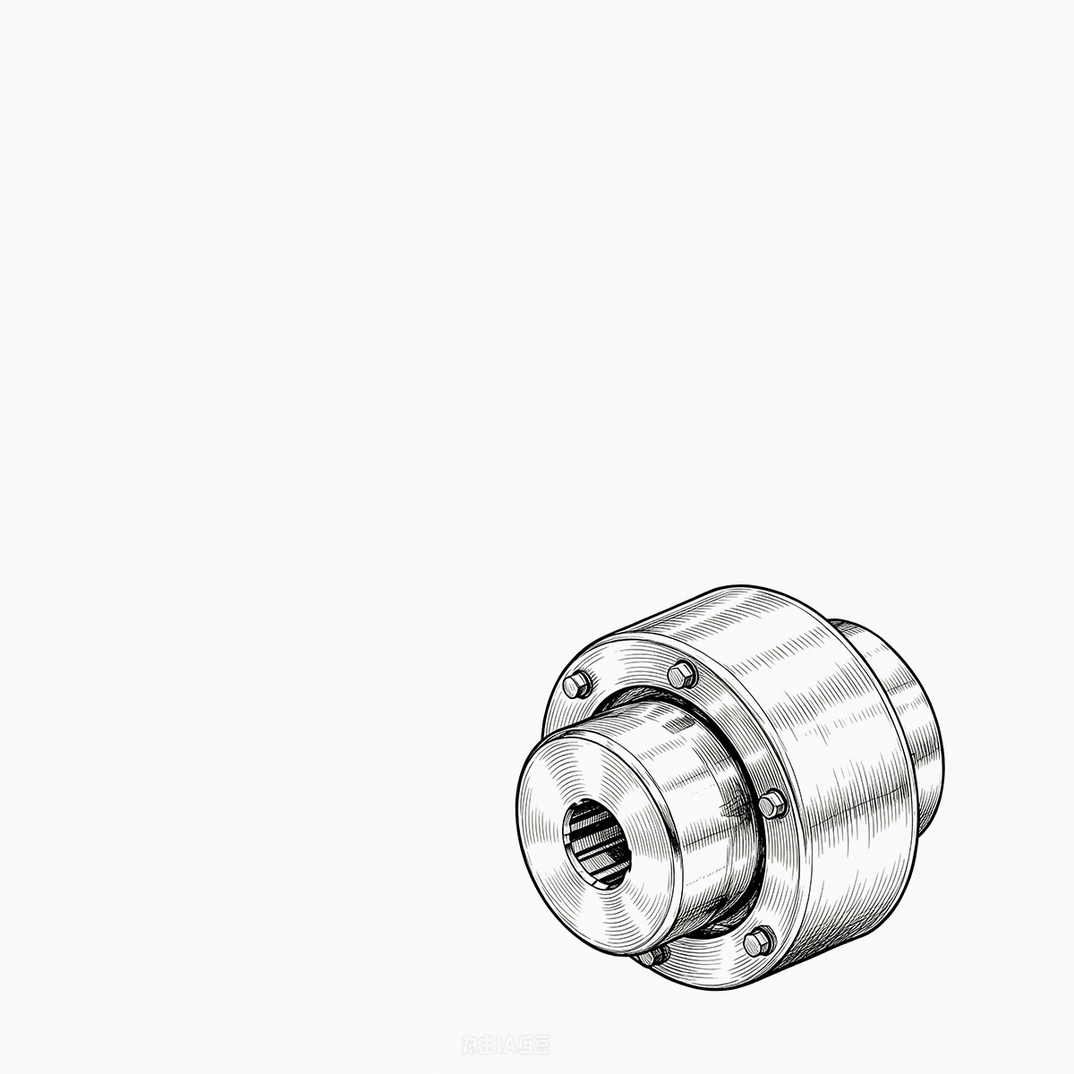
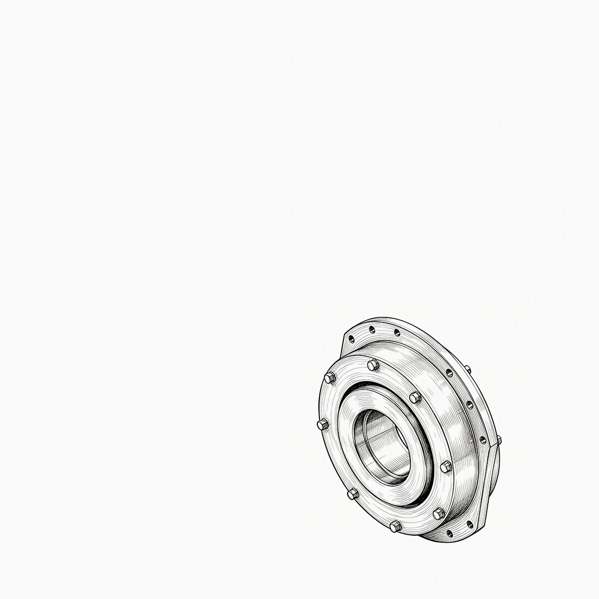

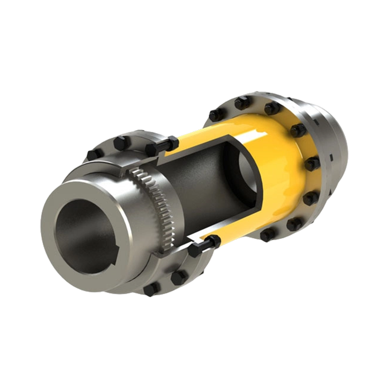
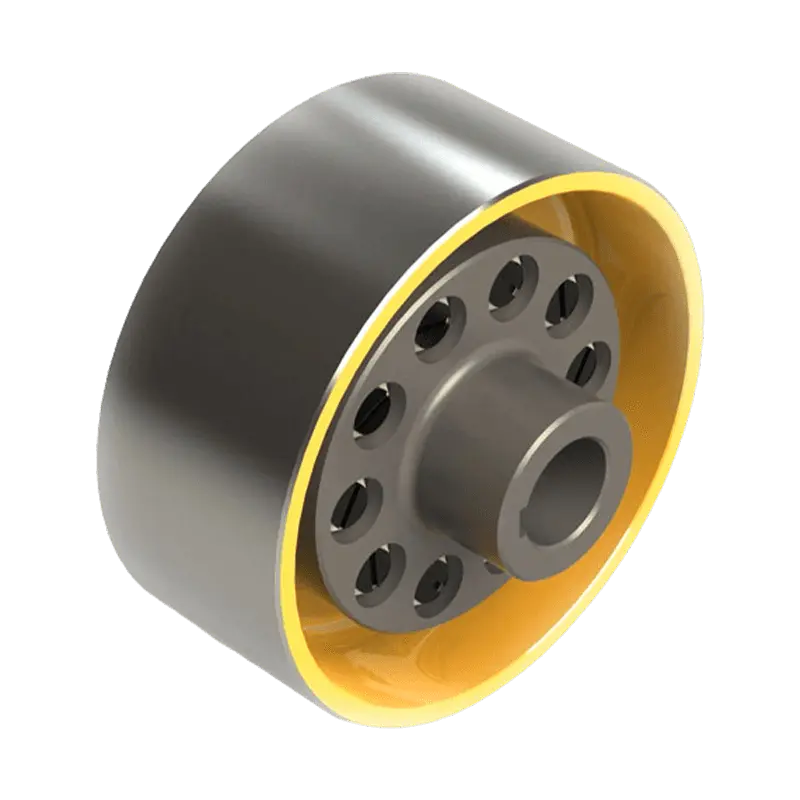
Consider a 250 kW crane hoist that begins to vibrate only when the load is lifted. The drum gear coupling is inspected ...
READ MORE
WGZ Crowned-Gear Coupling with Brake Wheel: Integrated Torque Transmission and Reliable Braking
Admin 2026-10-23Content
- 1 1. Product Overview
- 2 2. Why Crowned Gear Teeth Matter
- 3 3. Integrated Brake Wheel Design
- 4 4. Main Structural Components
- 5 5. Type I and Type II Sealing Configurations
- 6 6. Advantages Compared with Separate or Conventional Arrangements
- 7 7. Manufacturing Process and Quality Control
- 8 8. Orienthold Machinery’s Manufacturing Strengths
- 9 9. Application Areas
- 10 10. Selection Considerations
- 11 11. Installation Guidelines
- 12 12. Maintenance and Inspection
- 13 13. Safety Considerations
- 14 14. Customization and Technical Support
- 15 15. Frequently Asked Questions
- 15.1 Q1: What is the primary function of the WGZ crowned-gear coupling with brake wheel?
- 15.2 Q2: How does the crowned tooth profile improve performance?
- 15.3 Q3: Does the coupling eliminate the need for shaft alignment?
- 15.4 Q4: What is the advantage of the integrated brake wheel?
- 15.5 Q5: What is the difference between Type I and Type II?
- 15.6 Q6: Which industries commonly use this product?
- 15.7 Q7: Can the WGZ coupling be customized?
- 15.8 Q8: What should be checked during routine maintenance?
- 15.9 Q9: Is the brake drum suitable for every brake system?
- 15.10 Q10: Why is supplier manufacturing capability important for this type of coupling?
- 16 16. Conclusion
- 17 References
- 18 Product: WGZ Type Crowned-Gear Coupling with Brake Wheel
The WGZ Type Crowned-Gear Coupling with Brake Wheel is a heavy-duty mechanical power transmission component designed for equipment that demands high torque capacity, dependable misalignment compensation, and rapid braking response. By integrating a crowned-gear coupling with a brake drum, the WGZ design combines two important functions within one coordinated assembly: transmitting torque between connected shafts and providing a controlled braking surface for stopping or holding rotating equipment.
This integrated arrangement is particularly valuable in hoisting machinery, conveying systems, mining equipment, metallurgical installations, construction machinery, and large rotating systems. In these applications, a coupling is not simply a connection between two shafts. It must absorb or accommodate installation tolerances, shaft displacement, vibration, thermal movement, and changing loads while continuing to transfer power safely. At the same time, the braking system must respond quickly and maintain reliable contact with the rotating assembly during normal shutdowns or emergency stopping conditions.
The WGZ coupling addresses these requirements through a crowned-tooth gear structure, robust load-bearing components, dedicated sealing arrangements, and a brake wheel designed to work with shoe-type braking systems. Its structural integration can reduce the number of separate components in a drive system, simplify the overall arrangement, and support a more compact equipment layout. For machinery designers and maintenance teams, these characteristics can contribute to improved serviceability, better space utilization, and enhanced operating safety.
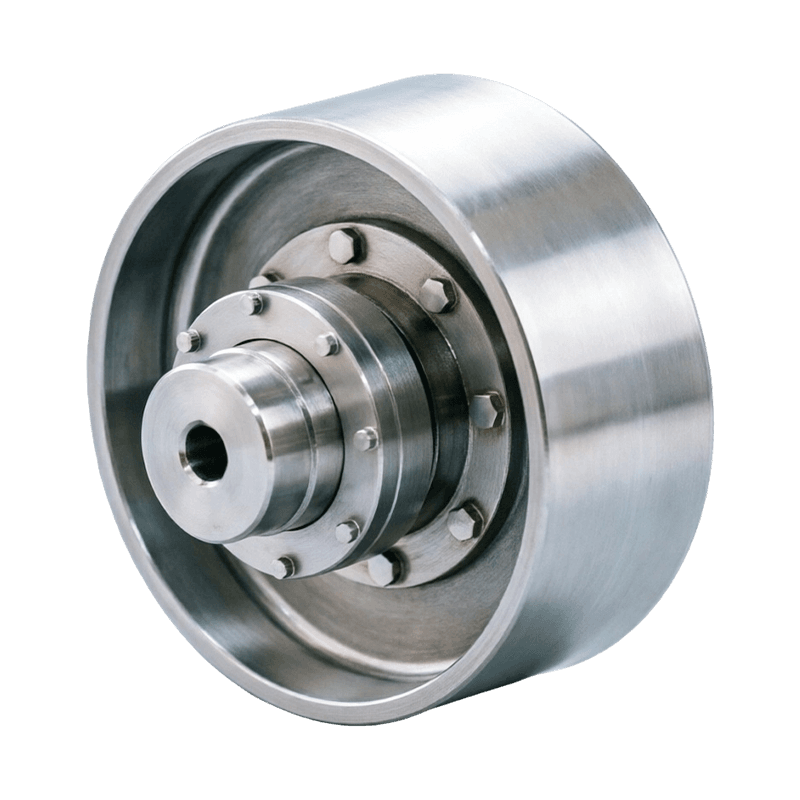
WGZ Type Crowned-Gear Coupling with Brake Wheel
1. Product Overview
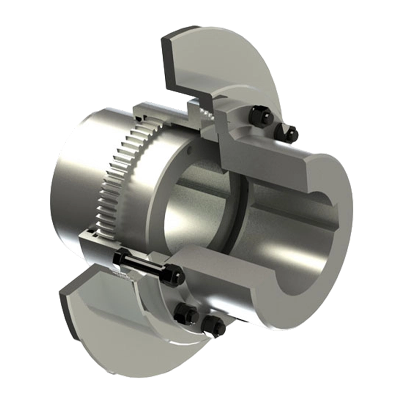
A gear coupling connects two shafts through the engagement of external and internal gear teeth. The coupling transmits torque while permitting a controlled amount of relative movement between the shafts. In the WGZ design, the external gear teeth have a crowned or spherical tooth profile. This profile is central to the coupling’s ability to tolerate radial, axial, and angular displacement without concentrating excessive stress at the edges of the teeth.
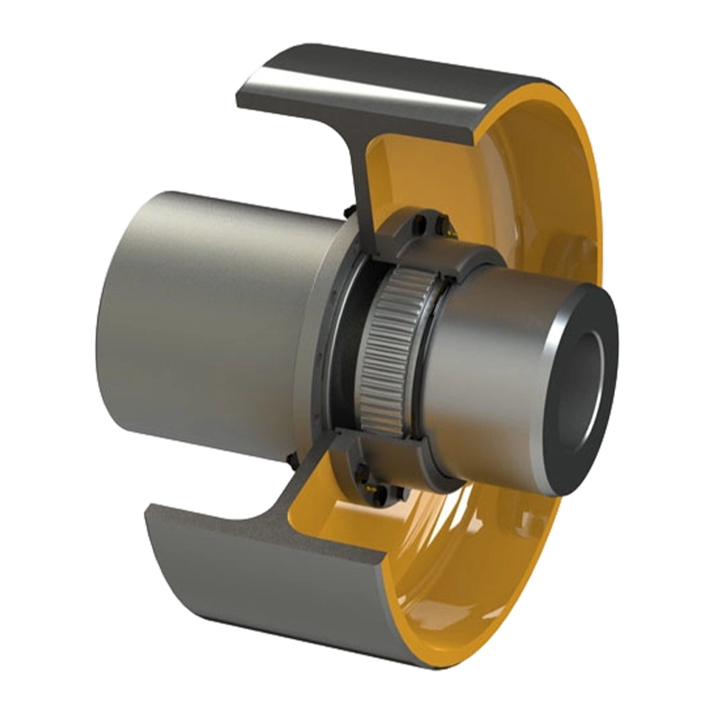
The main body of the WGZ coupling generally includes an external gear sleeve, an internal gear ring, an integrated brake drum, sealing assemblies, and associated fastening components. The external gear sleeve is connected to one shaft, while the internal gear ring is connected to the mating shaft. When the drive operates, the gear teeth engage and transfer torque through a broad contact area. The brake drum is rigidly connected with the coupling body and provides the working surface for external brake shoes.
During power transmission, the gear engagement carries the operating torque from the driving shaft to the driven shaft. During deceleration or shutdown, the brake shoes press against the brake drum and create frictional resistance. This resistance reduces rotational speed and can bring the connected machinery to a stop. Because the braking surface is incorporated into the coupling assembly, the transmission and braking functions are coordinated around the same rotating centerline.
The WGZ product is intended for demanding industrial conditions rather than light-duty applications. It is suitable for machinery where starting torque, stopping torque, shock loading, and operational continuity must be considered together. Typical examples include cranes, hoists, winches, conveyors, crushers, rolling equipment, lifting mechanisms, and other large systems that require positive control of rotating loads.
2. Why Crowned Gear Teeth Matter
Tooth geometry has a direct influence on the service life and reliability of a gear coupling. In a conventional straight-tooth arrangement, shaft misalignment can cause the mating teeth to contact primarily near one edge. Edge contact increases local pressure, accelerates wear, and may produce uneven loading across the engaged tooth surfaces. If the misalignment becomes significant, localized stress can cause pitting, scoring, deformation, or premature tooth failure.
The crowned tooth profile used in the WGZ coupling reduces this tendency. The external teeth are machined on a spherical surface whose center corresponds with the shaft axis. When the connected shafts move through a limited angular or radial displacement, the tooth surfaces can adjust their contact position. Instead of forcing the entire load through a narrow edge, the crowned geometry helps maintain a more favorable contact pattern.
This design does not eliminate the need for accurate shaft alignment. Proper installation remains essential for any high-torque coupling. However, it gives the system greater tolerance for the small deviations that occur in real machinery. These deviations may result from manufacturing tolerances, foundation movement, bearing clearance, thermal expansion, uneven loading, or deformation of supporting structures.
The crowned gear profile also helps reduce the risk of severe tooth-edge loading. More uniform load distribution can improve tooth surface durability and stabilize operating performance. In equipment subjected to repeated starts and stops, this advantage is especially important because transient loads can be considerably higher than the average running torque.
Misalignment Compensation
Industrial equipment rarely maintains perfect alignment throughout its complete operating life. Even a carefully aligned drive train may experience several forms of displacement:
Radial displacement occurs when the two shaft centerlines move parallel to one another but no longer coincide. This may be caused by bearing movement, foundation settlement, or mechanical deformation.
Angular displacement occurs when the two shaft centerlines intersect at an angle. It can result from assembly errors, shaft deflection, or movement of connected equipment.
Axial displacement occurs when one shaft moves along its length relative to the other. Thermal expansion, thrust movement, and changes in machine position may contribute to this condition.
The WGZ coupling is designed to accommodate controlled levels of these movements while continuing to transmit torque. The allowable displacement must always be evaluated according to the selected coupling size, operating speed, torque, lubrication condition, and manufacturer’s technical data. A coupling should not be used as a substitute for alignment correction, but its compensation capability provides valuable protection against unavoidable operating movement.
Improved Load Distribution
When gear teeth remain better distributed across their working surfaces, the effective contact pressure can be reduced. This may help limit adhesive wear, surface fatigue, and localized heating. A more balanced tooth contact pattern also supports smoother torque transfer and can reduce the likelihood of sudden changes in tooth loading.
For high-capacity machinery, this is a meaningful advantage over simpler rigid connections or less adaptable straight-tooth coupling designs. The result is not only a longer potential service life, but also more predictable maintenance behavior. Operators can inspect the coupling based on normal wear patterns instead of dealing with accelerated damage caused by repeated edge contact.
3. Integrated Brake Wheel Design
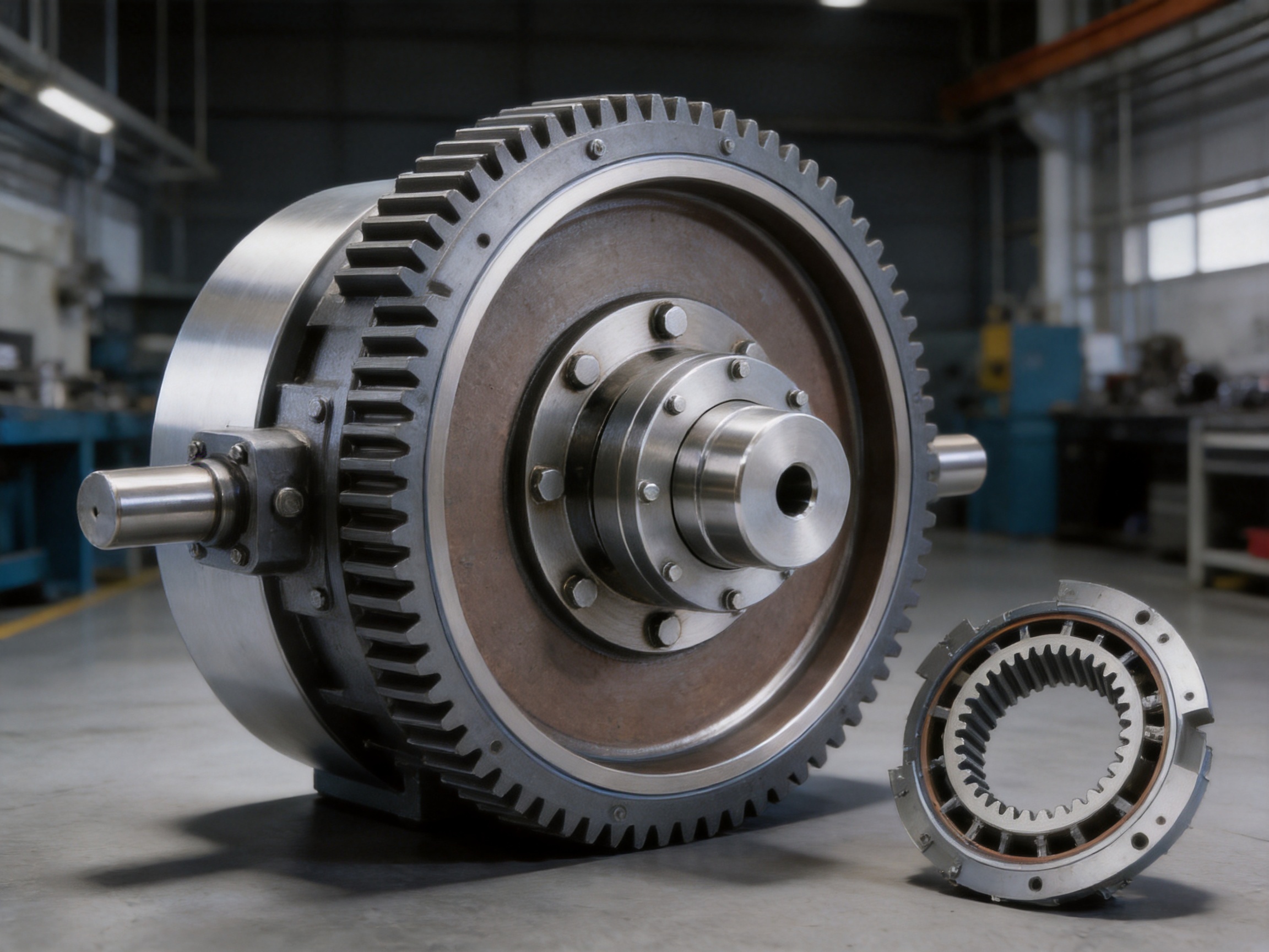
The defining feature of the WGZ model is its integrated brake wheel, also called a brake drum. A separate shaft coupling and brake drum can perform the same basic functions, but that arrangement may require additional shaft length, support structures, mounting hardware, and alignment work. The WGZ approach combines these functions into a coordinated component.
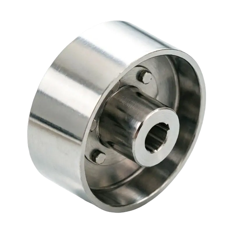
The brake drum is rigidly connected to the coupling body. It is designed to work with shoe-type braking systems, in which brake shoes move toward the drum and apply friction to its outer working surface. When the brake shoes engage, the friction force generates braking torque around the rotating axis. This torque slows the connected machinery and can ultimately hold the load in a stationary condition when the brake is correctly selected and adjusted.
An integrated brake wheel provides several potential system-level benefits. First, it can reduce the total number of rotating components. Second, it can make the transmission layout more compact. Third, it can reduce the need to install a separate brake drum on another portion of the shaft. Fourth, it can simplify the relationship between torque transmission and braking action by keeping both functions centered on the same coupling assembly.
These benefits are particularly useful in hoisting and conveying machinery. In a lifting application, the drive must transmit torque while the brake must control the suspended load. Any delay, structural flexibility, or unnecessary distance between the transmission and braking components can affect system behavior. By integrating the brake wheel into the coupling, designers can create a direct and mechanically coordinated arrangement.
Normal Shutdown and Emergency Braking
During normal shutdown, the brake shoes can be applied in a controlled sequence after the drive motor reduces speed. This approach can limit shock loading and help the equipment stop smoothly. In emergency conditions, the braking system may need to act rapidly to interrupt power transmission and prevent uncontrolled movement. The WGZ coupling provides the rotating brake surface required for either operating mode, provided that the brake shoes, actuator, control system, and coupling size are properly selected.
Braking performance depends on more than the coupling itself. Brake torque, drum diameter, shoe material, contact pressure, operating temperature, braking frequency, and load inertia must all be considered. The WGZ brake wheel is therefore one part of a complete braking system. Correct design and adjustment of the mating brake assembly remain essential to achieve the desired stopping time and holding capability.
Compact Arrangement and Space Efficiency
Space is often limited around gearboxes, motors, drums, and driven machinery. A separate brake drum may require a longer shaft, additional bearing support, or a different position in the drive train. The integrated WGZ structure can help reduce the axial length of the transmission arrangement and make better use of available installation space.
A more compact layout may also reduce the number of exposed interfaces. Fewer interfaces can mean fewer alignment points, fewer fasteners, and fewer opportunities for assembly errors. For original equipment manufacturers, this may simplify the design of the surrounding machine frame. For maintenance teams, it can make inspection and component replacement more straightforward.
4. Main Structural Components
External Gear Sleeve
The external gear sleeve transfers torque through its external crowned teeth. It is connected to one of the shafts and must withstand the combined effects of transmitted torque, bending influences, tooth contact forces, and operating shock. The gear sleeve is therefore manufactured with attention to dimensional accuracy, tooth profile, surface condition, and concentricity.
The external teeth must engage correctly with the internal gear ring throughout the expected range of movement. Accurate tooth machining helps maintain a stable contact pattern and reduces unnecessary backlash variation. The sleeve must also be compatible with the selected shaft connection, which may involve a keyed, splined, or other engineered mounting arrangement depending on the complete equipment design.
Internal Gear Ring
The internal gear ring mates with the external gear sleeve. Its internal teeth are shaped to maintain effective engagement with the crowned external teeth while allowing the coupling to compensate for controlled shaft displacement. The gear ring carries a substantial portion of the tooth contact load and must be manufactured with appropriate accuracy and material quality.
Internal gear components can be challenging to machine and inspect because the working teeth are located inside the ring. Reliable production therefore requires suitable tooling, controlled machining procedures, dimensional inspection, and careful verification of the tooth form. Any deviation in tooth geometry may affect load distribution, noise, wear, and service life.
Brake Drum
The brake drum is the friction surface for the external brake shoes. Its working diameter and width influence the available braking torque and heat dissipation characteristics. The drum must have a stable shape, sufficient stiffness, and a suitable surface condition for consistent contact with the brake shoes.
Because the brake drum rotates with the coupling, its balance and concentricity are important. Excessive runout can lead to uneven shoe contact, pulsating braking torque, vibration, and accelerated lining wear. Manufacturing and inspection procedures should therefore control the relationship between the drum surface and the coupling’s rotational centerline.
Sealing Assemblies
Gear couplings require protection against contamination and loss of lubricant. Sealing assemblies help retain lubricant around the tooth engagement and reduce the entry of dust, moisture, and abrasive particles. This is particularly important in mining, metallurgical, construction, and outdoor conveying environments where airborne contaminants may be present.
The sealing arrangement must accommodate the coupling’s movement without creating excessive friction or allowing lubricant leakage. Seal condition should be checked during routine maintenance. A damaged or hardened seal can allow contaminants into the gear chamber, which may accelerate tooth wear and reduce the effectiveness of lubrication.
5. Type I and Type II Sealing Configurations
The WGZ coupling is available in two principal sealing configurations: Type I with a split sealing end and Type II with an integral sealing end. The two configurations allow the product to be selected according to the equipment’s displacement requirements, installation limitations, and dynamic performance objectives.
Type I: Split Sealing End
Type I is characterized by a larger tooth spacing and a design that allows greater radial displacement compensation. It may be appropriate for equipment where shaft movement is relatively significant or where the connected machinery experiences greater structural deflection during operation.
The larger tooth spacing gives the coupling more room to accommodate movement between the mating components. This can be beneficial in large frames, long conveyor systems, heavy lifting mechanisms, and machines exposed to variable loading. As with all coupling designs, the actual permitted displacement must be confirmed from the relevant technical specifications before installation.
Type II: Integral Sealing End
Type II uses a more compact integral sealing arrangement. Its shorter or more integrated structure can reduce rotational inertia and support a compact installation. This configuration may be preferred where the drive must respond quickly to control commands or where the available installation space is restricted.
Lower rotational inertia can be valuable in systems that undergo frequent acceleration and deceleration. Reducing the rotating mass may help improve dynamic response and reduce the energy required to change speed. Type II can therefore be considered for machinery that places a premium on compactness, faster response, or reduced rotating weight.
| Feature | Type I | Type II | Typical Selection Consideration |
|---|---|---|---|
| Sealing arrangement | Split sealing end | Integral sealing end | Choose according to installation and movement requirements |
| Radial displacement capability | Greater compensation potential | Controlled compensation within a compact structure | Type I may suit equipment with greater structural movement |
| Structural form | More open tooth spacing | More compact configuration | Type II may suit limited installation space |
| Rotational inertia | May be comparatively higher | Lower rotational inertia potential | Type II can support quicker dynamic response |
| Typical application emphasis | Heavy movement and displacement tolerance | Compactness and responsive operation | Final selection should follow load and speed calculations |
6. Advantages Compared with Separate or Conventional Arrangements
Combined Transmission and Braking Functions
The most obvious advantage is functional integration. A conventional drive may use one coupling for torque transmission and another independently mounted drum for braking. The WGZ model combines these functions in one product family. This can simplify the mechanical architecture and reduce the number of components required around the shaft line.
Integration can also improve design coordination. When the coupling and brake drum are designed as one assembly, the rotational center, drum position, and coupling geometry are established together. This may reduce the risk of mismatched dimensions or unsuitable spacing between independently selected components.
Improved Misalignment Tolerance
Compared with rigid shaft connections, the crowned gear design allows the coupling to accommodate controlled displacement. This can protect connected equipment from the harmful effects of minor alignment errors and operating movement. The design is especially useful where high torque must be transmitted without making the shaft line completely inflexible.
Reduced Edge Loading
The crowned tooth profile helps maintain a more favorable contact pattern than a basic straight-tooth arrangement when displacement occurs. Reduced edge loading can support improved wear behavior and more stable tooth surface contact. This advantage becomes increasingly important as torque, shaft size, and operating duty increase.
Suitable for Heavy-Duty Service
The WGZ coupling is intended for industrial machinery that experiences demanding mechanical loads. Its structure is suitable for applications where shock, vibration, frequent starting, and braking must be considered. Heavy-duty suitability does not mean that the coupling can be operated beyond its rated capacity. Instead, it indicates that the product architecture is designed around the requirements of large and highly loaded drive systems.
Compact Installation
The integrated brake wheel can reduce the need for a separate drum installation. This may shorten the shaft arrangement, reduce supporting hardware, and simplify machine-frame design. Compactness can also make it easier to protect the rotating assembly with guards while maintaining access for inspection.
Potential Maintenance Benefits
With fewer separate components, maintenance personnel may have fewer interfaces to inspect. A unified coupling and brake assembly can make it easier to establish a regular inspection routine covering tooth condition, lubrication, sealing, drum surface, fastening, and alignment. A clear inspection plan remains necessary because the product contains both transmission and braking functions.
7. Manufacturing Process and Quality Control
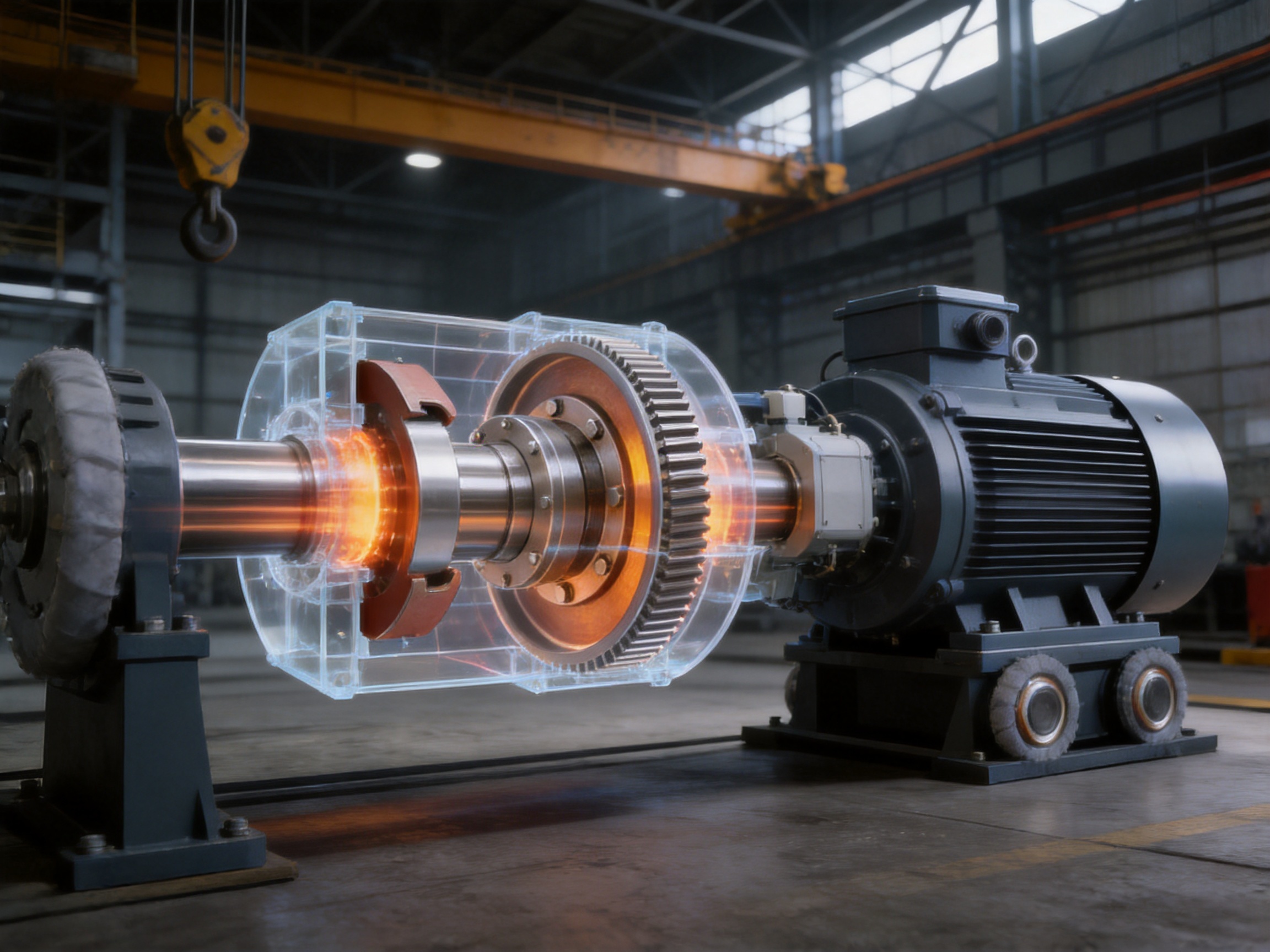
The performance of a high-capacity coupling depends heavily on manufacturing precision. Gear tooth geometry, drum concentricity, sealing fit, material condition, and assembly accuracy all influence the product’s behavior in service. Orienthold Machinery integrates design, production, and service, allowing the company to manage the product development and manufacturing process as a connected engineering activity.
Engineering and Product Design
Manufacturing begins with a clear understanding of the application. Engineers must consider transmitted torque, peak torque, operating speed, braking torque, shaft dimensions, misalignment, duty cycle, ambient conditions, lubrication, and installation limitations. For crane and hoisting equipment, load inertia and stopping behavior are especially important. For conveyors and mining equipment, contamination, shock loading, and long operating periods may receive greater emphasis.
The crowned gear profile, brake drum dimensions, sealing arrangement, and connection details are developed as part of an integrated structure. This approach helps ensure that the transmission function and braking function are not treated as unrelated design tasks. It also allows the selected Type I or Type II configuration to match the intended operating environment.
Material Preparation
Material selection must reflect the loads and environmental conditions expected in service. Gear components require sufficient strength and wear resistance, while the brake drum requires dimensional stability and a suitable friction surface. Material preparation may include identification, cutting, preliminary inspection, and control of the workpiece condition before machining.
Good material management supports consistent production. Traceability of workpieces, controlled storage, and inspection of incoming materials help reduce the possibility that material variation will affect the finished coupling. The precise material grade and heat treatment should be selected according to the product specification and application requirements.
Precision Machining
The gear sleeve and internal gear ring require careful machining to achieve the intended tooth profile. The crowned geometry must be produced accurately so that the teeth can accommodate movement without creating unacceptable contact concentration. Internal and external gear machining operations must be coordinated to maintain correct working clearance and engagement.
The brake drum is also machined to control its diameter, width, surface condition, and concentricity. A drum that is not sufficiently round or that has excessive runout may cause uneven braking. Machining therefore supports both mechanical transmission performance and braking consistency.
Other important machining controls include shaft bore dimensions, keyway or connection geometry, flange relationships, bolt-hole positioning, and overall axial dimensions. These features influence installation accuracy and the ability of the finished coupling to fit within the customer’s equipment.
Heat Treatment and Surface Performance
Where specified by the product design, heat treatment can be used to improve the strength, hardness, and wear resistance of gear components. The treatment must be controlled so that the component achieves the required mechanical properties without excessive distortion. Subsequent finishing or corrective machining may be necessary to restore dimensional accuracy.
Surface quality is particularly important at tooth flanks and the brake drum. Rough or damaged surfaces may increase friction, accelerate wear, and make lubrication less effective. Controlled finishing processes support stable contact and help the coupling perform consistently across repeated operating cycles.
Inspection and Testing
Orienthold Machinery operates with a quality supervision system supported by inspection and testing equipment. Inspection can cover dimensional accuracy, tooth geometry, concentricity, runout, surface condition, sealing fit, assembly quality, and overall appearance. The exact inspection plan depends on the product model and customer requirements.
Testing is not limited to checking individual parts. The assembled coupling must also be evaluated as a functional unit. The relationship between the gear components and the brake wheel is important because any assembly error can affect both torque transmission and braking performance. A structured inspection process helps identify issues before shipment and supports consistent production between batches.
Assembly Control
Assembly personnel must ensure that the external gear sleeve, internal gear ring, sealing assemblies, brake drum, fasteners, and related components are correctly positioned. Lubricant should be applied according to the specified method and quantity. Overfilling may increase churning losses or pressure within the sealed area, while insufficient lubricant may accelerate tooth wear.
Fasteners must be tightened using an appropriate sequence and method. The coupling should be checked for smooth movement, correct engagement, and signs of interference. Where required, assembly records and inspection results can support traceability and customer quality documentation.
8. Orienthold Machinery’s Manufacturing Strengths
Zhenjiang Orienthold Machinery Co., Ltd. is a medium-sized enterprise specializing in couplings and papermaking machinery. The company integrates design, production, and service, allowing it to support customers from initial product selection through delivery, installation guidance, and after-sales maintenance.
The company serves industries including transportation, metallurgy, chemical engineering, mining, construction, and hoisting. These industries require components that can operate under variable loading, severe working conditions, and demanding maintenance schedules. Experience across these fields supports a practical understanding of how couplings are selected and used in complete machines.
Orienthold Machinery emphasizes technical capability, advanced production equipment, and comprehensive testing methods. These resources are important for crowned gear couplings because the product’s performance depends on the relationship between several precision features rather than on one simple dimension. Tooth profile, concentricity, sealing, brake drum geometry, and assembly quality must all be controlled together.
The company also operates under a strict quality supervision system. Its products comply with applicable national standards, and its technical resources support the production of industrial equipment for customers in different markets. Quality supervision is reinforced by inspection and testing equipment intended to verify product consistency before shipment.
Another important strength is customization. Industrial drive systems often have different shaft sizes, torque requirements, brake arrangements, installation dimensions, and environmental conditions. A supplier that can discuss these variables before production is better positioned to provide a suitable coupling solution. Orienthold Machinery provides pre-sales consultation and customization support to help customers match product characteristics with machine requirements.
The company’s one-stop service approach includes technical consultation, customized production, flexible logistics and payment options, and maintenance support. This can reduce communication gaps between design, manufacturing, and service activities. For overseas customers and equipment manufacturers, a coordinated supplier relationship can be valuable when the coupling is part of a larger project schedule.
9. Application Areas
Hoisting and Crane Equipment
Hoisting machinery places high demands on both torque transmission and braking. The drive may need to accelerate a suspended load, maintain controlled motion, stop quickly, and hold the load securely. The WGZ coupling’s integrated brake wheel is well suited to this type of arrangement when matched with an appropriate shoe brake and control system.
Crane travel mechanisms, lifting mechanisms, winches, and trolley drives may benefit from the coupling’s ability to accommodate controlled displacement. The crowned gear teeth can help compensate for movement caused by frame deflection, bearing conditions, or installation tolerances.
Conveying Systems
Large conveyors may operate for long periods and transport heavy or variable loads. Starting and stopping can impose significant torque variation on the drive train. A crowned gear coupling provides flexibility between the motor, gearbox, and driven pulley, while the brake wheel supports controlled stopping where required.
In inclined conveyors, the braking function can be especially important because gravity may cause the belt or load to continue moving after power is removed. The brake system must be correctly designed for the conveyor’s load, slope, speed, and stopping requirements.
Mining Machinery
Mining environments may expose equipment to dust, vibration, shock, moisture, and difficult maintenance conditions. A robust gear coupling with effective sealing can help protect the tooth engagement from contamination. The integrated brake wheel can support safe control of large rotating and conveying mechanisms.
Mining equipment should be evaluated carefully for environmental protection, lubrication intervals, guarding, inspection access, and brake lining compatibility. The coupling is one element in a wider reliability strategy that includes proper machine design and planned maintenance.
Metallurgical Equipment
Metallurgical machinery often operates under high loads, elevated temperatures, vibration, and frequent production cycles. Rolling equipment, transfer systems, lifting devices, and other large machines require strong and adaptable shaft connections. The WGZ coupling can be considered where high torque, misalignment compensation, and braking control are required together.
Construction Machinery
Construction machinery may experience changing loads, repeated starts and stops, and rough operating conditions. The compact structure of the WGZ model can help designers fit the coupling into restricted spaces while retaining a dedicated braking surface. Proper guarding is essential because both the gear coupling and brake drum are rotating components.
Large Rotating Systems
Fans, drums, processing machines, and other large rotating systems may require a flexible high-torque connection. The crowned gear design allows a controlled degree of movement while maintaining power transmission. If the machine requires rapid stopping or parking control, the brake wheel can be integrated into the drive arrangement.
10. Selection Considerations
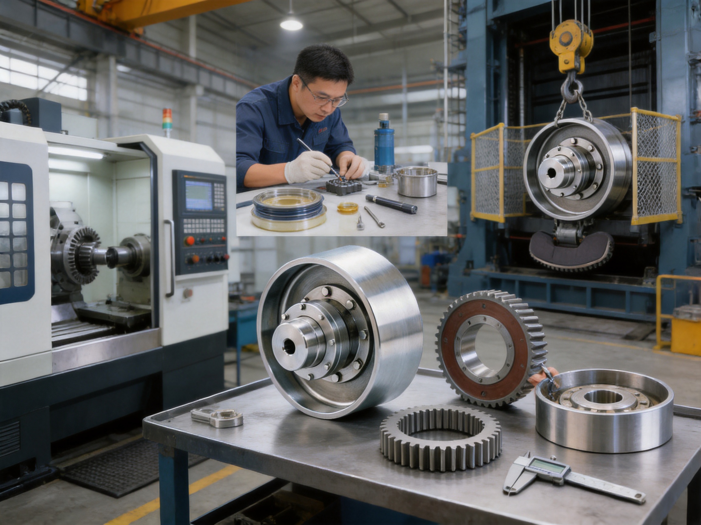
Choosing the correct WGZ coupling requires more than matching shaft diameter. The selection should begin with the normal operating torque and then consider starting torque, peak torque, shock loading, operating speed, duty cycle, braking torque, and expected misalignment.
The coupling’s rated capacity should exceed the actual operating requirement with an appropriate service factor. The service factor should reflect the machine type, load variation, start frequency, reversing operation, impact, and braking conditions. Equipment used for heavy lifting or repeated shock loading may require a substantially different selection from equipment with smooth, continuous rotation.
Brake selection must be coordinated with the coupling. The brake drum diameter, available friction area, brake shoe force, stopping time, load inertia, and thermal duty must be evaluated together. A brake that is too small may not stop the load reliably, while excessive braking torque can impose unnecessary shock on the coupling and connected machinery.
Operating speed must also be considered. Higher speed increases the importance of balance, concentricity, sealing performance, lubrication, and guarding. If the equipment experiences frequent acceleration and deceleration, rotational inertia becomes more significant, particularly when comparing Type I and Type II configurations.
Environmental conditions should be reviewed before specifying seals and lubrication. Dust, water, corrosive materials, high temperature, low temperature, and outdoor exposure may influence the suitable configuration and maintenance plan. The coupling should be protected from direct contamination wherever possible.
Installation dimensions are another important factor. Engineers should verify shaft spacing, shaft extension, coupling outside diameter, brake shoe clearance, guard dimensions, access for lubrication, and removal space. A technically suitable coupling may still be impractical if there is insufficient room for inspection or replacement.
11. Installation Guidelines
Before installation, inspect the shafts, keys, bores, mounting surfaces, fasteners, and coupling components. Remove burrs, rust, dirt, and shipping protection that could interfere with accurate assembly. Confirm that the coupling size, sealing configuration, and brake wheel dimensions match the equipment drawings.
Align the connected shafts as accurately as practical using suitable measurement equipment. The crowned gear profile provides compensation for operating displacement, but it should not be relied upon to correct major installation errors. Excessive initial misalignment can produce unnecessary tooth loading and reduce service life.
Install the coupling according to the specified shaft connection and fastening procedure. Check that the gear components engage smoothly and that the coupling can move through its intended compensation range without binding. Confirm that the brake drum is concentric and that the brake shoes have the correct clearance before commissioning.
Apply the specified lubricant to the gear engagement. Use only a lubricant compatible with the coupling, seals, operating temperature, and speed. The lubricant should be clean and free from water or abrasive contamination. Close and secure the sealing assemblies properly after lubrication.
Install guards around the rotating coupling and brake wheel. Guards should prevent accidental contact while allowing appropriate inspection access. The brake actuator, shoe movement, and release mechanism should be checked before the machine is operated at full load.
12. Maintenance and Inspection
A planned maintenance program helps preserve the coupling’s transmission and braking functions. Inspection intervals should be based on operating hours, duty cycle, environment, start-stop frequency, and the consequences of failure. Heavy-duty lifting and mining equipment may require more frequent inspections than lightly loaded continuous-duty machinery.
Check for lubricant leakage around the sealing assemblies. Leakage may indicate seal wear, improper installation, excessive internal pressure, or damage to the sealing surface. Also inspect for dust, water, metal particles, or other contaminants that may have entered the coupling.
Inspect the gear teeth for pitting, scoring, abnormal polishing, cracking, deformation, or uneven wear. A narrow wear band or damage concentrated at one edge may indicate excessive misalignment or an unsuitable operating condition. Any unusual pattern should be investigated rather than ignored.
Inspect the brake drum for scoring, cracking, excessive wear, heat discoloration, or uneven contact marks. Check the brake shoes for lining wear, contamination, cracking, and correct adjustment. The drum and shoes should contact evenly across the intended working area.
Check coupling fasteners, shaft connections, keys, guards, and supporting components. Loose fasteners or movement at the shaft connection can create vibration and rapidly damage the coupling. Vibration, abnormal noise, temperature increase, delayed stopping, or changes in braking behavior should be treated as warning signs requiring prompt inspection.
Lubrication intervals should follow the product documentation and actual service conditions. High loads, high speeds, frequent starts, and contaminated environments may require more frequent attention. When relubricating, avoid mixing incompatible lubricant types and ensure that old contaminated lubricant is managed appropriately.
13. Safety Considerations
The WGZ coupling and brake wheel are rotating machine elements and must be guarded during operation. Personnel should never approach an exposed coupling or brake drum while the equipment is running. Lockout and isolation procedures should be followed before inspection, lubrication, adjustment, or repair.
Braking systems must be tested as part of commissioning and routine maintenance. A brake that engages too slowly, releases incompletely, or fails to hold the load presents a serious hazard. The control system, actuator, brake shoes, drum surface, and coupling should be evaluated as one safety-related assembly.
Emergency stopping requirements should be established during machine design. The brake must be capable of handling the load inertia and expected stopping frequency without overheating or losing effectiveness. If the machine handles suspended loads, additional protective measures may be required according to the applicable equipment standards and risk assessment.
Replacement parts should be correctly matched to the original coupling model and operating requirements. Improvised modifications to the brake drum, gear components, seals, or mounting arrangement can compromise both mechanical strength and braking reliability.
14. Customization and Technical Support
Industrial customers may require customized coupling dimensions or a configuration adapted to a particular machine. Typical engineering information includes motor power, gearbox ratio, shaft diameter, shaft spacing, operating speed, nominal torque, peak torque, braking torque, start frequency, ambient conditions, and allowable installation space.
Providing complete application information helps the supplier evaluate the appropriate coupling size and sealing configuration. It also allows potential issues to be identified before production, such as insufficient brake clearance, excessive shaft movement, inadequate lubrication space, or conflicts with surrounding guards.
Orienthold Machinery supports customers with pre-sales consultation and customized solutions. Its combined experience in couplings and industrial machinery allows technical discussions to address not only the coupling itself but also its relationship with motors, gearboxes, brakes, drums, bearings, and machine frames.
After delivery, maintenance guidance and service support can help customers establish suitable inspection and lubrication routines. A long-term supplier relationship is particularly useful for equipment manufacturers that need consistent coupling supply across multiple machine models or projects.
15. Frequently Asked Questions
Q1: What is the primary function of the WGZ crowned-gear coupling with brake wheel?
The product transmits torque between two connected shafts while providing an integrated brake drum for use with shoe-type braking systems. It combines flexible gear coupling performance with a dedicated braking surface in one assembly.
Q2: How does the crowned tooth profile improve performance?
The crowned profile allows the tooth contact area to adjust when controlled radial, axial, or angular displacement occurs. This can reduce tooth-edge loading, improve load distribution, and support longer tooth surface durability compared with a basic straight-tooth arrangement.
Q3: Does the coupling eliminate the need for shaft alignment?
No. The coupling compensates for limited operating displacement, but accurate initial alignment remains essential. Excessive installation misalignment can cause abnormal tooth loading, vibration, wear, and reduced service life.
Q4: What is the advantage of the integrated brake wheel?
The integrated brake wheel combines braking and torque transmission functions in one coordinated assembly. It can reduce the need for a separate brake drum, save installation space, simplify the drive layout, and support direct braking of the coupling’s rotating assembly.
Q5: What is the difference between Type I and Type II?
Type I uses a split sealing end and provides greater radial displacement compensation potential through larger tooth spacing. Type II uses an integral sealing end and offers a more compact structure with lower rotational inertia potential. The correct choice depends on displacement, space, speed, and dynamic response requirements.
Q6: Which industries commonly use this product?
Typical industries include hoisting, cranes, conveying, mining, metallurgy, construction, transportation, chemical engineering, and other sectors using large rotating machinery. The product is suited to applications requiring high torque transmission and controlled braking.
Q7: Can the WGZ coupling be customized?
Customization may be available according to shaft dimensions, torque, speed, braking requirements, installation space, sealing needs, and other application parameters. Customers should provide complete technical data so that the coupling can be selected or designed appropriately.
Q8: What should be checked during routine maintenance?
Maintenance personnel should inspect gear tooth wear, lubricant condition, seal integrity, brake drum surface, brake shoe contact, fasteners, shaft connections, alignment, vibration, and unusual noise or temperature. The inspection interval should reflect the machine’s duty and environment.
Q9: Is the brake drum suitable for every brake system?
The drum is designed for compatibility with shoe-type braking systems, but the complete brake must still be selected according to drum dimensions, braking torque, shoe force, stopping time, heat generation, and control requirements. Compatibility should be confirmed before installation.
Q10: Why is supplier manufacturing capability important for this type of coupling?
A high-capacity crowned gear coupling contains several precision relationships, including tooth geometry, concentricity, sealing fit, drum runout, and assembly accuracy. Strong manufacturing equipment, inspection systems, engineering experience, and quality supervision help ensure consistent performance across these features.
16. Conclusion
The WGZ Type Crowned-Gear Coupling with Brake Wheel is a practical solution for heavy-duty machinery requiring both reliable power transmission and controlled braking. Its crowned gear teeth help accommodate controlled shaft displacement and reduce the risk of concentrated edge loading. Its integrated brake drum supports shoe-type braking while reducing the need for a separate braking component.
The product offers potential advantages in torque capacity, misalignment tolerance, compactness, layout simplicity, and operational safety. Type I and Type II configurations provide options for different displacement, sealing, space, and dynamic response requirements. Correct selection remains essential and must account for torque, speed, braking duty, environment, alignment, and installation dimensions.
Orienthold Machinery strengthens the product offering through integrated design, production, testing, customization, and service capabilities. Its experience serving transportation, metallurgy, chemical engineering, mining, construction, hoisting, and other industrial sectors supports the practical application of coupling technology in demanding machinery.
When correctly selected, installed, lubricated, guarded, and maintained, the WGZ coupling can contribute to a more compact and dependable drive system. For equipment manufacturers and industrial users seeking a coordinated solution for transmission and braking, it provides a strong alternative to separate conventional components.
References
1. Industrial Gear Coupling Design Principles and Misalignment Compensation, technical reference material.
2. Mechanical Power Transmission Equipment: Coupling Selection, Installation, and Maintenance Practices.
3. Industrial Braking Systems: Shoe Brakes, Brake Drums, Torque Requirements, and Thermal Considerations.
4. Gear Tooth Contact, Load Distribution, and Surface Wear in Flexible Couplings, engineering reference material.
5. Machinery Alignment and Rotating Equipment Reliability, maintenance engineering reference.
6. General National Standards and Technical Specifications Applicable to Industrial Couplings and Mechanical Transmission Components.
7. Manufacturer’s Product Information for WGZ Type Crowned-Gear Couplings with Brake Wheels.
Product: WGZ Type Crowned-Gear Coupling with Brake Wheel
PREV: No previous articleNEXT: Industrial Couplings: Precision Power Transmission for Demanding Applications
Be the First to Know
For exclusive deals and latest offers, sign up by entering your email address below.
Related products
News
-
-
Two quotes land for the same replacement gear coupling: $1,850 from one shop and $2,600 from another. Both promise stan...
READ MORE -
Gear Coupling vs. Drum Gear Coupling: The Core Difference The main difference is that "gear coupling" is a broad catego...
READ MORE -
A mill drive rarely fails without warning. It knocks at speed, throws a smear of dark grease around the sleeve flange, ...
READ MORE -
China's coupling industry is at a critical historical juncture of transformation from scale expansion to quality and eff...
READ MORE -
During a routine vibration survey on a high-speed compressor train, engineers found a 4.5 mm/s velocity spike at the mo...
READ MORE


ABOUT US
PRODUCTS
INDUSTRIES
CONTACT US
- Phone: +86-18652865511
- Email: sales@ohmach.com
- Address: No.1, Minying Developing Zone, Zhenjiang, Jiangsu, China
Copyright Zhenjiang Orienthold Machinery Co., Ltd. All Rights Reserved.
 Custom Industrial Shaft Coupling Manufacturers