 English
 русский
 Português
 عربى

Industrial Couplings: The Definitive Technical Encyclopedia – Classification, Sizing, Failure Prevention, and Lifecycle...
READ MORE
SWC-CH Long Telescopic Welded Universal Coupling for Demanding Industrial Drives
Admin 2026-08-28Content
- 1 Why Complex Industrial Drives Need More Than a Rigid Connection
- 2 Product Construction and Operating Principle
- 3 Key Performance Advantages
- 4 Comparison with Alternative Coupling Solutions
- 5 Applications in Heavy Industry
- 6 Manufacturing Strengths and Quality Control
- 7 Customization for Different Drive Requirements
- 8 Installation Recommendations
- 9 Maintenance and Inspection Program
- 10 Selection Guide for Engineers and Purchasing Teams
- 11 Operational and Economic Benefits
- 12 Frequently Asked Questions
- 12.1 What is the main purpose of the SWC-CH coupling?
- 12.2 What does “long telescopic” mean?
- 12.3 What angle can the coupling accommodate?
- 12.4 Why is a welded body advantageous?
- 12.5 What materials are used for the universal-joint components?
- 12.6 Is the SWC-CH suitable for crane applications?
- 12.7 Can the coupling be customized?
- 12.8 How often should the coupling be lubricated?
- 12.9 What are the signs of coupling wear?
- 12.10 Can the coupling correct poor installation alignment?
- 12.11 What information is needed for product selection?
- 12.12 Which industries commonly use this type of coupling?
- 13 Why Choose an Experienced Coupling Manufacturer
- 14 Conclusion
- 15 References
- 16 Product: SWC-CH Long Telescopic Welded Universal Coupling
Reliable power transmission becomes increasingly difficult when machinery must operate under high torque, severe vibration, substantial impact loads, angular misalignment, and axial movement at the same time. Conventional rigid shaft connections can transmit torque effectively when alignment is ideal, but they may transfer excessive loads to connected equipment when thermal expansion, installation tolerances, foundation movement, or dynamic deflection changes the shaft relationship. A coupling intended for these conditions must do more than connect two shafts. It must accommodate movement, maintain torque transmission, resist fatigue, protect associated equipment, and remain serviceable during long periods of industrial operation.
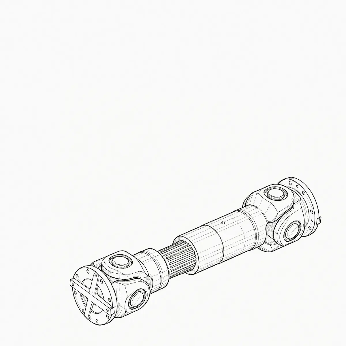
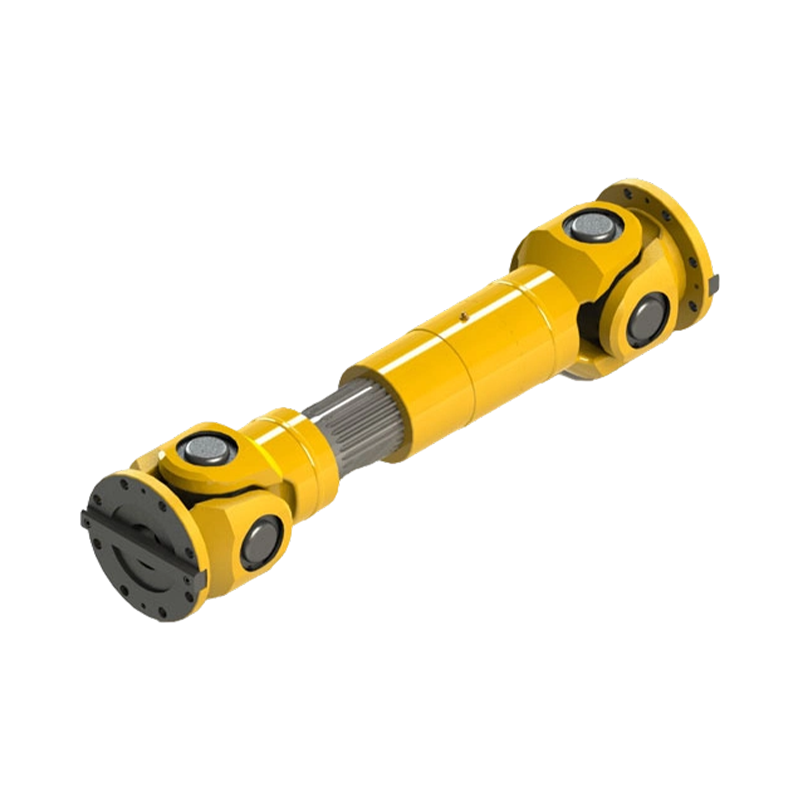
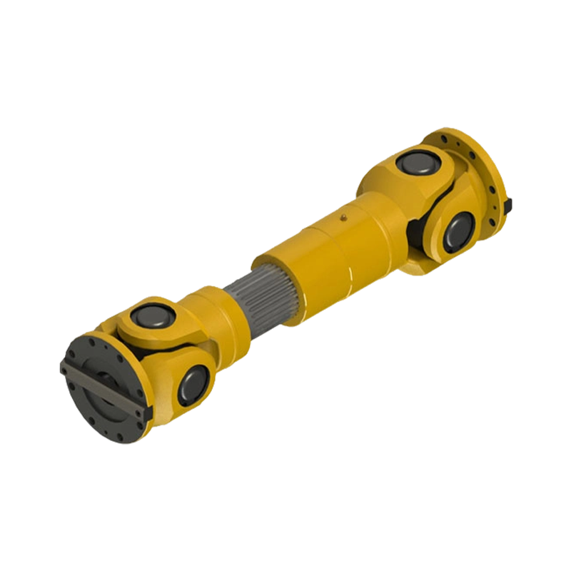
The SWC-CH Long Telescopic Welded Universal Coupling is designed for precisely this type of application. Classified as a cross universal coupling, it combines angular compensation, axial displacement capacity, a long telescopic structure, and a welded body. The result is a transmission component suited to heavy-duty equipment in transportation, metallurgy, mining, construction, hoisting, and other industries where operating conditions are demanding and downtime is costly.
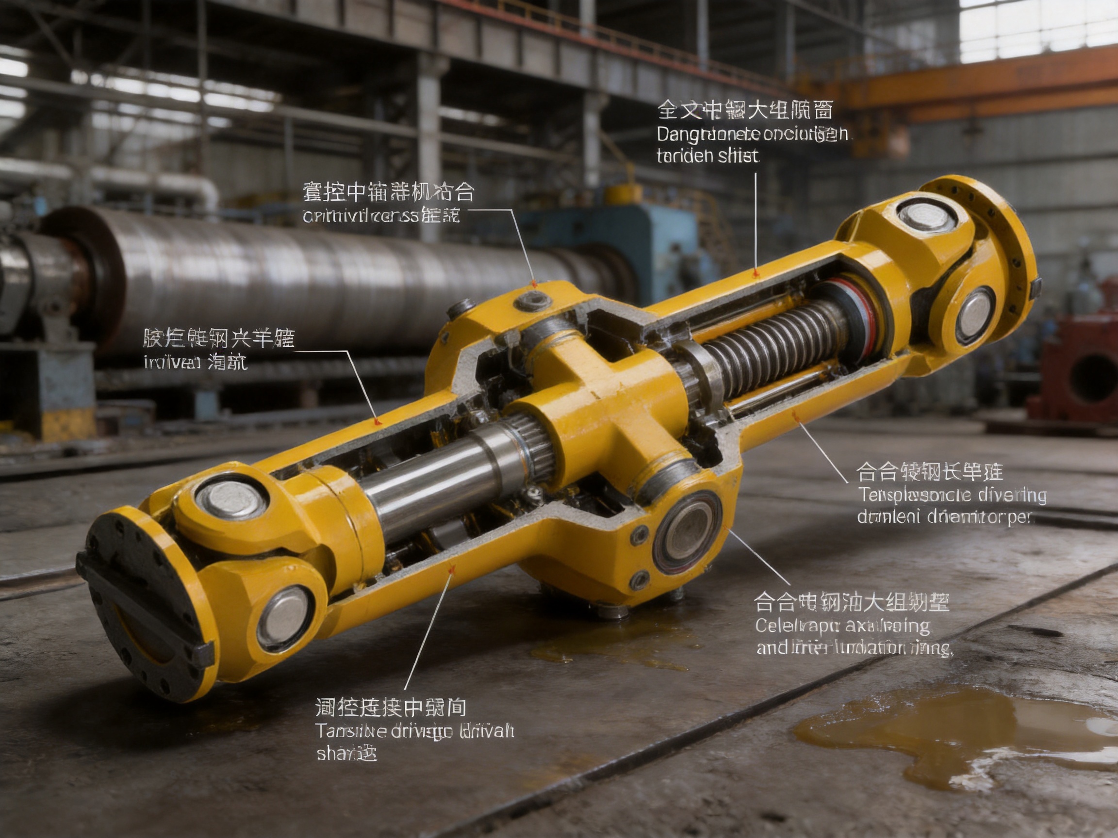
Its design brings together a flange connection end, telescopic spline set, cross universal joint, welded body, and lubrication system. Each element performs a specific mechanical function, while the complete assembly works as an integrated system. The universal joint accommodates angular deflection, the telescopic spline set compensates for axial movement, the welded body provides structural strength, and the lubrication arrangement supports smooth movement and wear control.
Compared with basic fixed couplings, short telescopic couplings, or designs that rely mainly on bolted body connections, the SWC-CH offers a broader compensation range and a more robust construction concept. It is particularly valuable where shafts cannot remain perfectly aligned throughout the operating cycle and where the coupling must continue transmitting power during repeated movement and impact.
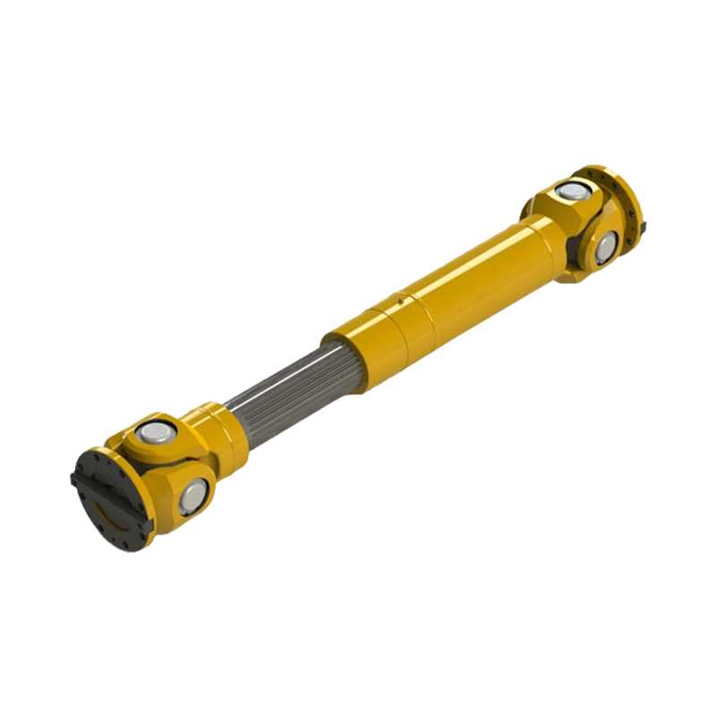
SWC-CH Long Telescopic Welded Universal Coupling
Why Complex Industrial Drives Need More Than a Rigid Connection
Industrial shafts rarely operate in a perfectly static geometry. Even when equipment is carefully installed, the distance and angle between connected shafts can change during operation. Temperature causes shafts and machine frames to expand. Heavy loads deflect structures. Bearings develop small changes in position. Crane mechanisms move through different positions. Rolling and conveying equipment may experience repeated shock loads. Mining and construction machinery often operate under variable loads and uneven foundations.
A rigid shaft connection cannot absorb these changes without transferring reaction forces to the bearings, gearboxes, motors, drums, or driven machines. The result may be accelerated bearing wear, gear tooth damage, shaft fatigue, vibration, seal failure, or unexpected shutdown. A conventional flexible coupling may reduce some of these effects, but not every flexible coupling can simultaneously handle a large operating angle, significant axial movement, and high torque.
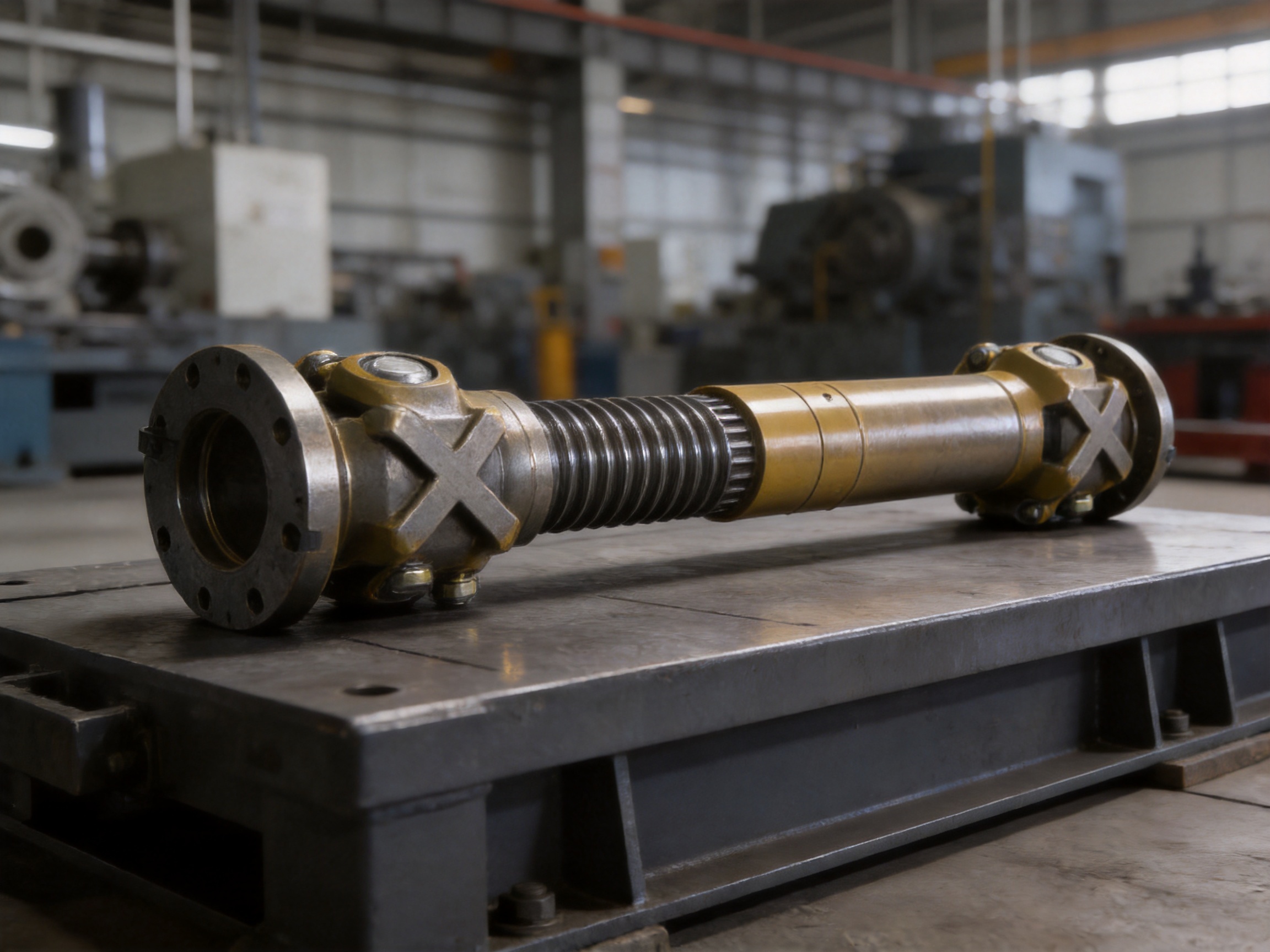
The function of a universal coupling is to transmit rotational power between shafts that are not collinear. Its cross universal joint allows angular deflection while preserving mechanical connection. When a telescopic section is added, the coupling can also change its effective length as the connected shafts move axially. These two functions are especially important in long shaft arrangements and equipment where the operating position varies.
The SWC-CH design extends this concept through a long telescopic configuration and a welded body. The long body provides useful axial travel and installation flexibility, while the welded construction supports rigidity and torsional resistance. The coupling is therefore not merely a flexible connector; it is a structural transmission assembly engineered for dynamic industrial service.
Product Construction and Operating Principle
Flange Connection End
The flange connection end provides the interface between the coupling and the shafts or connected machine components. A flange arrangement distributes transmitted torque through a broad connection area and allows the coupling to be integrated with different types of industrial equipment. Depending on the application, the connection may be adapted to the shaft diameter, bolt arrangement, installation space, and required service conditions.
A properly designed flange connection is essential because the coupling can only perform effectively when torque is transferred evenly into the connected shafts. Accurate machining, correct bolt installation, suitable fits, and proper alignment all contribute to reducing local stress concentration. For customized projects, connection dimensions can be reviewed according to the customer’s equipment drawings and operating requirements.
Telescopic Spline Set
The telescopic spline set provides the axial compensation function. It allows one section of the coupling to slide relative to another while continuing to transmit torque. This movement is necessary when shafts change their relative position because of thermal expansion, machine displacement, installation variation, or operating deflection.
The SWC-CH telescopic structure uses an involute tooth profile. Involute splines are well suited to torque transmission because the tooth geometry supports controlled contact and smooth engagement. Precise clearance control is important: excessive clearance may generate impact, noise, and uneven wear, while insufficient clearance may restrict axial movement or cause binding. A carefully controlled spline fit allows the coupling to extend and retract without sacrificing the ability to transmit industrial loads.
The long telescopic arrangement is particularly advantageous where the expected axial movement is greater than that handled by a compact coupling. It can also simplify installation by providing additional adjustment during assembly. Instead of forcing connected machines into a precise fixed distance, technicians may be able to use the telescopic section to accommodate the required shaft spacing within the approved design range.
Cross Universal Joint
The cross universal joint is the primary component responsible for angular compensation. It enables torque transmission when the connected shafts operate at an angle to one another. The cross and bearing elements must resist repeated alternating loads while maintaining smooth rotation under changing positions.
For demanding applications, high-strength alloy steel is used for the main universal-joint components, followed by precision heat treatment and surface strengthening. These processes improve hardness, toughness, fatigue resistance, and resistance to contact wear. The objective is not simply to make the material harder. A properly controlled treatment process balances surface durability with internal toughness so that the component can resist repeated loading without becoming excessively brittle.
The typical angle compensation range of the SWC-CH is approximately 15 to 25 degrees, depending on the specific configuration and operating conditions. When two universal-joint stages are arranged in series, the overall system can accommodate more complex shaft geometry and improve alignment capability. The actual allowable angle should always be confirmed through engineering review because speed, torque, lubrication, duty cycle, and joint geometry influence the permissible operating limit.
Welded Body
The welded body connects and supports the major coupling components. Compared with a body made primarily from bolted sections, a welded structure can offer improved rigidity and torsional strength when it is correctly designed and manufactured. A rigid body helps maintain the relative position of the internal components and reduces deformation under high load.
Welding also reduces the number of mechanical joints that could loosen under vibration. In heavy-duty machinery, repeated impact and alternating torque can challenge bolted connections, particularly if installation torque, surface condition, or maintenance is not ideal. A properly executed welded body minimizes these potential looseness points and can improve sealing continuity around the assembly.
However, welded construction must be supported by disciplined process control. Welding sequence, joint preparation, filler material, heat input, distortion control, and inspection all influence the final performance. The strength of the SWC-CH does not come from welding alone; it comes from combining suitable structural design with controlled fabrication and verification.
Lubrication System
Universal joints and telescopic splines operate through repeated sliding, rolling, and contact motion. Adequate lubrication reduces friction, controls heat generation, limits surface damage, and helps remove wear particles from critical contact zones. The lubrication system is therefore a functional part of the coupling rather than an optional accessory.
Service intervals depend on speed, transmitted torque, operating angle, ambient temperature, contamination, duty cycle, and the selected lubricant. In dusty or wet environments, maintenance planning becomes especially important. A suitable lubrication procedure should include cleaning around grease points, using the specified lubricant, checking for leakage, and observing signs of contamination or abnormal wear.
Key Performance Advantages
Large-Angle Power Transmission
The SWC-CH is designed for applications where the shafts cannot be maintained in a straight-line arrangement. Its cross universal joint supports angular movement while maintaining torque transmission. This is a major advantage over rigid couplings, which normally require very accurate alignment and offer little tolerance for operating deflection.
Large-angle capability is valuable in equipment with moving frames, long shaft lines, articulated structures, or machines where the driving and driven components are located at different elevations. It can reduce the need for complicated intermediate support arrangements and provide greater freedom in equipment layout.
Long Axial Compensation
The long telescopic section compensates for axial displacement that may develop during operation. Thermal expansion is a common example. A long shaft or machine frame may grow as temperature increases, changing the distance between connected components. Without axial compensation, this expansion can create compressive or tensile forces in the shaft line.
The SWC-CH allows controlled axial sliding through its spline set. This movement helps reduce unwanted axial loads and prevents the coupling from acting as an unintended restraint. The same function can accommodate installation errors and dynamic displacement, provided that the movement remains within the approved stroke and load range.
High Torsional Rigidity
High torsional rigidity helps the coupling transmit torque efficiently and maintain stable rotational behavior. The welded body supports structural stiffness, while the spline and flange interfaces transfer the driving force through designed contact surfaces. This is useful in applications where torque changes rapidly or where startup and stopping produce high transient loads.
Rigid torque transmission can also support better control of machine timing. In conveying, lifting, rolling, and processing equipment, excessive torsional deflection may create speed variation, impact, or synchronization problems. A well-designed coupling helps preserve the intended relationship between the drive and driven shafts.
Resistance to Impact and Vibration
Heavy industrial machinery often experiences shock loads that are not visible in a simple steady-state torque calculation. Crane mechanisms may start and stop repeatedly. Mining machines may encounter irregular material loads. Metallurgical equipment may operate at high temperatures and under substantial mechanical resistance. These conditions require a coupling with adequate fatigue strength and structural stability.
The combination of alloy-steel universal-joint components, heat treatment, a strong welded body, and controlled spline engagement gives the SWC-CH a suitable foundation for impact-prone service. Correct selection remains essential: the coupling must be sized according to peak torque, not only nominal motor power.
Improved Sealing and Connection Stability
A welded body can reduce potential leakage paths and reduce the number of body joints susceptible to loosening. Better sealing helps retain lubricant and limits the entry of dust, moisture, and other contaminants. This benefit is especially relevant in outdoor equipment, material-handling systems, mining operations, and environments with airborne particles.
Connection stability also supports predictable maintenance. When the body and flange interfaces remain secure, technicians can focus inspection on normal wear areas such as the spline teeth, cross bearings, seals, and fasteners rather than repeatedly correcting structural looseness.
Longer Service Potential
Service life depends on operating conditions and maintenance, but the SWC-CH incorporates several features intended to support durability. The involute spline profile distributes torque through multiple teeth. Heat-treated alloy steel improves resistance to contact and fatigue damage. The welded body limits structural movement. Lubrication reduces friction and surface distress.
These features work together. A strong material cannot compensate for poor lubrication, and an accurate spline cannot compensate for excessive operating angle. The coupling’s service potential is highest when design selection, installation, lubrication, alignment, and inspection are treated as one complete maintenance system.
Comparison with Alternative Coupling Solutions
Industrial coupling selection should be based on the movement and load conditions of the complete machine. No coupling type is superior in every situation. The SWC-CH is especially competitive when the application requires a combination of angular compensation, axial travel, high torque, and heavy-duty construction.
| Coupling solution | Angular compensation | Axial compensation | Heavy-duty suitability | Typical limitation |
|---|---|---|---|---|
| Rigid flange coupling | Very limited | Very limited | High under precise alignment | Transfers misalignment loads to connected equipment |
| Short flexible coupling | Limited to moderate | Limited | Suitable for controlled conditions | May not provide sufficient travel for long shaft systems |
| Gear coupling | Moderate | Moderate, depending on design | High torque capability | Requires careful lubrication and may be sensitive to contamination |
| Disc coupling | Limited to moderate | Limited to moderate | Good for clean, accurately aligned systems | Less suitable for severe shock and large operating angles |
| Universal coupling without long telescopic travel | High | Limited to moderate | Good for angular shaft arrangements | May not accommodate substantial axial displacement |
| SWC-CH long telescopic welded universal coupling | Approximately 15–25 degrees, configuration dependent | Long telescopic compensation | Designed for heavy and high-impact service | Requires correct sizing, lubrication, and inspection |
Compared with Rigid Couplings
Rigid couplings are simple and efficient when shafts are accurately aligned and remain fixed relative to one another. They may be appropriate for stable foundations, low movement, and controlled operating conditions. However, they offer little protection against thermal growth or dynamic displacement. If the machine geometry changes, the rigid coupling can transfer excessive loads to bearings and shafts.
The SWC-CH provides a more forgiving connection. Its universal joint addresses angular movement, while its telescopic spline set addresses axial movement. This makes it a more suitable alternative for machinery in which alignment changes are expected rather than exceptional.
Compared with Conventional Gear Couplings
Gear couplings are widely used for transmitting high torque and can provide a degree of angular and axial flexibility. Nevertheless, many gear coupling designs rely on toothed sleeves and hubs that require consistent lubrication and protection from contamination. Their practical performance may decline when seals deteriorate or maintenance access is poor.
The SWC-CH uses a cross universal joint as its central angular-transmission mechanism and incorporates a long telescopic spline arrangement. This architecture is particularly beneficial when large shaft angles and substantial axial movement are primary design requirements. The welded body can also provide a more structurally integrated assembly than a multi-piece bolted housing.
Compared with Disc Couplings
Disc couplings are valued for low backlash, clean operation, and suitability for accurately aligned systems. They are often selected for instrumentation, high-speed drives, and applications where maintenance-free operation is important. However, disc elements can be sensitive to excessive angular displacement, axial movement, and repeated shock loads.
For heavy machinery with large movement and impact, the SWC-CH offers a more robust compensation concept. It is not intended to replace every disc coupling, but it has a clear advantage when the operating environment is too severe for thin flexible discs or when the shaft angle exceeds the practical range of a compact precision coupling.
Compared with Short Telescopic Universal Couplings
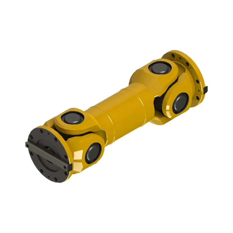
A short telescopic universal coupling may be adequate when the axial movement is small and the installation envelope is compact. A long telescopic design becomes more valuable when the shaft spacing is large, thermal expansion is substantial, or the machine experiences repeated axial displacement.
The SWC-CH’s extended telescopic structure can provide additional compensation and installation flexibility. It may also reduce the need for separate shaft adjustment mechanisms. The correct choice depends on the required stroke, retracted length, extended length, torque, speed, and available space.
Applications in Heavy Industry
Transportation and Conveying Equipment
Conveyors, transfer systems, loading equipment, and other transportation machinery often use long shaft arrangements. Frames may flex under load, and drive components may be separated by considerable distances. A long telescopic universal coupling can compensate for changes in shaft position while maintaining power transmission.
In systems that start and stop frequently, the coupling must also tolerate torque changes and repeated acceleration. Correctly selected flange dimensions and universal-joint capacity are important for preventing local overload at the drive or driven equipment.
Metallurgical Machinery
Metallurgical equipment may combine high torque, elevated temperature, vibration, scale, and heavy structural loads. Rolling mills and related machines can experience dynamic displacement and substantial impact during material entry. Thermal expansion may also be significant because of hot-process conditions.
The SWC-CH is well suited to applications where the transmission system must accommodate both angular and axial movement. Its welded body and heat-treated transmission components support the demands of continuous industrial operation, while its lubrication system helps protect sliding and bearing surfaces.
Mining Equipment
Mining machinery operates in environments where dust, uneven foundations, shock loading, and variable material resistance are common. Conveying, crushing, screening, and material transfer systems may expose couplings to substantial vibration and contamination.
A coupling for mining service must be mechanically strong and maintainable. The SWC-CH can be integrated into heavy-duty drive systems where its telescopic capacity helps absorb movement and its universal joint supports non-collinear shaft arrangements. Protective covers, appropriate sealing, and a clearly defined lubrication schedule are recommended for dusty environments.
Construction Machinery
Construction equipment frequently changes position and operates on uneven ground. Structural deflection and movement can affect the relationship between the drive and driven shafts. A universal coupling with axial compensation can reduce the mechanical consequences of this movement.
The SWC-CH may be considered for large construction machines, transfer mechanisms, hoisting equipment, and other systems requiring durable torque transmission under variable loading. Application review should include shock factors, operating speed, travel frequency, and environmental exposure.
Crane and Hoisting Systems
Crane mechanisms require dependable transmission because failure can interrupt production and create safety risks. Hoisting, traveling, and luffing systems may experience repeated starts, stops, reversals, and load changes. Shaft alignment can also vary as structures deflect or move through their operating range.
The SWC-CH provides angular flexibility and axial compensation for such changing geometry. The coupling must be selected using the actual service factor, maximum lifted load, acceleration pattern, braking torque, and duty classification. Periodic inspection is essential because hoisting applications often involve high consequence of failure.
Industrial Processing Lines
Processing lines may include several machines connected through long transmission routes. Differences in equipment elevation, thermal behavior, and foundation settlement can create alignment challenges. The coupling’s telescopic section provides a way to manage controlled axial movement without imposing excessive force on adjacent machinery.
For processing applications, engineers should also consider washdown conditions, corrosive substances, ambient temperature, speed range, and compatibility of seals and lubricants. The basic coupling architecture can be adapted when the environment requires additional protection or special materials.
Manufacturing Strengths and Quality Control
The performance of a welded universal coupling depends heavily on manufacturing consistency. A coupling may have an attractive design on paper, but variations in material quality, machining accuracy, weld integrity, heat treatment, or assembly can reduce its reliability. Zhenjiang Orienthold Machinery Co., Ltd. integrates design, production, and service so that these stages can be coordinated rather than treated as separate activities.
Engineering and Application Review
The manufacturing process begins with understanding the operating conditions. Important information includes transmitted torque, peak torque, rotational speed, shaft angle, axial movement, shaft diameter, connection dimensions, duty cycle, ambient temperature, contamination, installation arrangement, and available maintenance space.
Engineering review helps determine whether a standard configuration is suitable or whether customization is required. A coupling intended for a moderate-speed conveyor may require a different configuration from one used in a reversing crane mechanism or a high-impact metallurgical drive. The ability to review drawings and operating data before production helps reduce the risk of selecting an unsuitable coupling.
Material Selection
Material selection is matched to the function of each component. High-strength alloy steel is used for critical universal-joint parts where fatigue strength, toughness, and wear resistance are important. Structural sections are selected to provide appropriate rigidity and weldability. Flanges and spline components require material properties compatible with the expected torque and contact stress.
Material traceability and inspection provide a foundation for consistent production. Depending on the order and specification, material checks may include certificate review, dimensional verification, hardness testing, and other quality-control procedures. Consistent raw materials help ensure that later machining and heat-treatment results remain predictable.
Precision Machining
Machining accuracy directly affects coupling performance. Spline tooth geometry, flange faces, bearing seats, cross-joint interfaces, and shaft bores must be produced within appropriate dimensional tolerances. Poor concentricity can increase vibration, while inaccurate spline clearance can restrict telescopic movement or create impact between teeth.
Advanced production equipment supports repeatable machining of critical surfaces. Inspection methods may include dimensional measurement, runout checks, surface-finish verification, and fit evaluation. These controls are especially important for long couplings because small errors can have a greater effect over an extended shaft line.
Controlled Welding Processes
Welding is a central feature of the SWC-CH construction. The fabrication sequence must limit distortion and maintain the designed geometry. Weld preparation, positioning, preheating where required, heat input, interpass control, and post-weld inspection all influence structural integrity.
After welding, the body may require dimensional correction, stress management, machining of reference surfaces, and inspection for visible or internal defects. The objective is to create a strong and stable body that supports the rotating elements without introducing excessive runout or residual deformation.
Heat Treatment and Surface Strengthening
Universal-joint components and spline parts are exposed to repeated contact stress. Precision heat treatment can improve the balance between hardness and toughness, while surface strengthening can increase resistance to wear and fatigue at high-contact areas.
Heat-treatment control includes temperature management, holding time, cooling method, and hardness verification. The selected process depends on the material and component geometry. Consistency is essential because over-hardening can reduce toughness, while insufficient hardness may shorten wear life.
Assembly and Dynamic Verification
Assembly requires correct positioning of the cross universal joint, spline components, flange parts, seals, and lubrication elements. Incorrect assembly can lead to uneven load distribution or accelerated wear even when every individual component meets its dimensional requirements.
Final inspection may include visual checks, dimensional verification, rotation checks, runout measurement, lubrication confirmation, and other tests defined by the project specification. For critical applications, customers may request additional inspection records or performance verification. A complete testing approach provides greater confidence than relying on visual inspection alone.
Integrated Service Capability
Orienthold Machinery operates as a medium-sized enterprise specializing in couplings and papermaking machinery. Its production and service structure supports communication between design engineers, manufacturing personnel, quality staff, and customers. This integrated approach can be valuable when a coupling must be adapted to a particular machine rather than selected solely from a general catalog.
The company serves industries including transportation, metallurgy, chemical engineering, mining, construction, and hoisting. Its stated quality system includes inspection and testing equipment, national-standard compliance, and service covering consultation, customization, logistics, payment coordination, and maintenance support.
Customization for Different Drive Requirements
Industrial couplings often need to match existing equipment rather than a universal installation standard. Customization may involve flange dimensions, shaft bores, spline travel, overall length, protective arrangements, lubrication points, surface treatment, or material selection.
Customers should provide a complete technical data package whenever possible. The most useful information includes motor power, operating speed, nominal and peak torque, shaft angle, required axial stroke, shaft-end dimensions, installation distance, duty classification, ambient conditions, and maintenance expectations.
For systems with frequent reversing, the torsional and fatigue loads may differ significantly from those in a continuously rotating drive. For high-speed systems, balance and runout become more critical. For low-speed, high-torque equipment, structural strength and bearing loads may dominate the selection. Custom engineering should reflect the actual operating profile rather than relying on nominal power alone.
Protective covers may be recommended when personnel could contact rotating components or when the coupling operates in a contaminated environment. Additional sealing may be considered for dust, water, scale, or process residue. Corrosion-resistant surface treatment may be appropriate for outdoor or chemically exposed equipment.
Installation Recommendations
Preparation Before Installation
Before installation, verify the coupling model, connection dimensions, shaft condition, flange condition, fastener grade, lubricant, and available axial movement. Inspect all parts for transport damage and remove protective coatings only where required for assembly. Dirt, burrs, and paint on mating surfaces can affect alignment and connection quality.
Measure the shaft positions in the actual installation state. The centerline, angular relationship, and distance between shaft ends should be compared with the approved drawing. The telescopic section should not be forced beyond its intended range during installation.
Flange and Fastener Assembly
Flange surfaces should be clean and seated evenly. Fasteners must be tightened in the correct sequence and to the specified torque. Uneven tightening may distort the flange or create uneven torque distribution. Where the design requires locking devices, they should be installed and checked before commissioning.
Do not use the coupling to correct major foundation or shaft alignment errors. Its flexibility is intended to accommodate controlled operating movement, not compensate for poor installation. Excessive initial misalignment can significantly reduce the life of the universal joint and spline system.
Lubrication and Protective Components
Apply the approved lubricant to the universal-joint bearings and telescopic spline areas according to the manufacturer’s instructions. Confirm that grease passages are open and that seals are correctly positioned. Protective covers should be fitted where specified and should not interfere with telescopic movement or rotating clearance.
Trial Operation
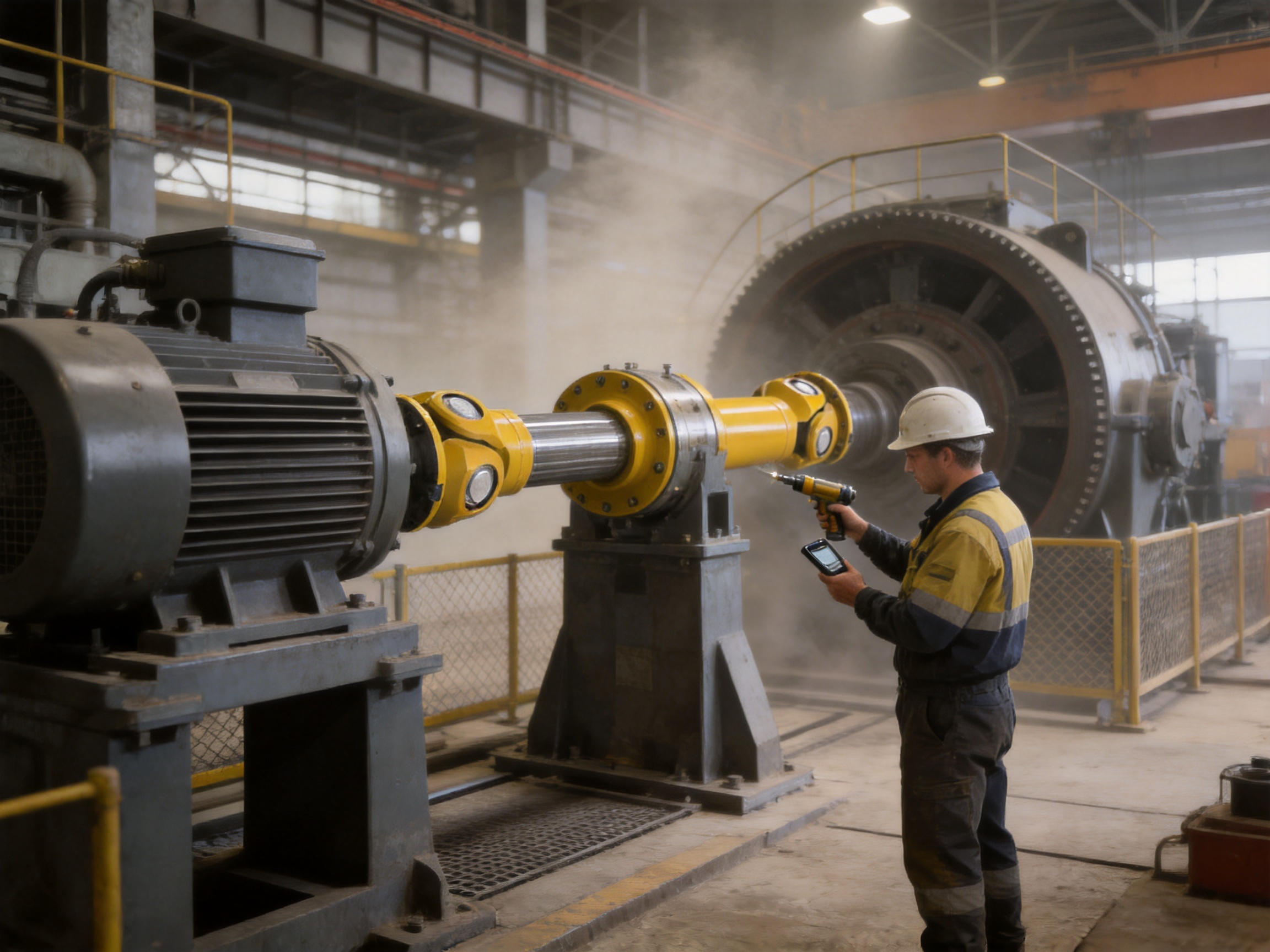
After installation, operate the equipment at low speed when possible. Observe for abnormal vibration, noise, heat, grease leakage, binding, or irregular telescopic motion. Gradually increase the load while monitoring the coupling and connected equipment.
If abnormal conditions appear, stop the equipment and investigate before continuing. Common causes include incorrect flange seating, excessive shaft angle, insufficient lubrication, uneven fastener tightening, damaged seals, or a coupling length that does not match the operating position.
Maintenance and Inspection Program
A maintenance program should be based on operating severity. A coupling used in a clean, continuous-duty system may require a different inspection interval from one installed on a reversing crane or dusty mining machine. Inspection frequency should increase during the initial operating period, after major repairs, and whenever abnormal vibration or noise is reported.
Routine Visual Inspection
Inspect the welded body for cracks, deformation, corrosion, and impact damage. Check the flange joints and fasteners for looseness or movement marks. Examine seals for leakage, hardening, tearing, or displacement. Verify that protective covers remain secure and that no foreign material has entered the moving parts.
Spline Inspection
Check the telescopic spline for smooth axial movement when the equipment is safely isolated. Excessive backlash, rough sliding, metallic particles in lubricant, or local tooth damage may indicate wear or misalignment. Spline wear should not be judged only by appearance; measurable clearance and operating symptoms should also be considered.
Universal-Joint Inspection
Listen for clicking, knocking, or cyclic noise during operation. These symptoms may indicate bearing wear, inadequate lubrication, excessive angle, or damage to the cross assembly. Monitor operating temperature and compare it with previous readings. A gradual increase may indicate friction, seal failure, overload, or insufficient lubricant.
Lubricant Management
Use only a lubricant compatible with the coupling materials, seals, temperature, speed, and load. Mixing incompatible greases can reduce lubrication performance. Before replenishing, clean the grease point to prevent contamination from entering the coupling.
Over-lubrication should also be avoided. Excess grease can increase churning, pressure, and seal stress. The maintenance procedure should specify the lubricant type, quantity, interval, and application method.
Condition-Based Monitoring
For critical equipment, vibration monitoring, temperature measurement, torque observation, and periodic alignment checks can provide early warning of developing faults. Trends are often more useful than a single measurement. A gradual increase in vibration or temperature may reveal wear before visible damage occurs.
Maintenance records should include inspection date, operating hours, lubricant condition, measured clearances, observed symptoms, and corrective actions. These records support better replacement planning and help identify repeated installation or operating problems.
Selection Guide for Engineers and Purchasing Teams
Selecting the correct SWC-CH configuration requires more than matching shaft diameter. The following points should be reviewed before ordering:
Torque and Service Factor
Determine nominal torque from the motor or prime mover, then consider startup torque, braking torque, overload, reversing duty, impact, and operating cycle. The selected coupling should have sufficient capacity for the highest realistic transmitted torque, not merely the average value.
Operating Angle
Measure the shaft angle under actual operating conditions. If the angle changes during movement, identify both the minimum and maximum values. The typical 15 to 25 degree compensation range is configuration dependent, and higher angles may require a double-stage arrangement or a different design review.
Axial Stroke
Calculate the total required axial movement, including thermal expansion, installation tolerance, structural deflection, and dynamic displacement. The coupling should not operate continuously at the absolute end of its telescopic travel. An appropriate reserve should be maintained to prevent bottoming or disengagement.
Speed and Balance
Rotational speed affects universal-joint loads, lubrication behavior, vibration, and balance requirements. Long couplings may be more sensitive to runout and dynamic imbalance. The required speed range should be stated clearly during technical evaluation.
Environment
Describe exposure to dust, water, chemicals, heat, cold, scale, abrasive particles, and outdoor weather. Environmental information influences sealing, lubricant selection, surface treatment, material choice, and inspection frequency.
Installation and Maintenance Access
Confirm the available installation space, lifting method, retracted and extended coupling length, access to grease points, and removal procedure. A coupling that performs well mechanically can still create operational problems if it cannot be installed or serviced safely.
Operational and Economic Benefits
The value of a heavy-duty coupling is measured not only by purchase price but also by its effect on the complete machine. A coupling that accommodates movement can reduce loads on bearings and shafts. A strong structure can reduce unplanned repairs. A serviceable lubrication system can support predictable maintenance. A stable transmission connection can help preserve production quality and operating efficiency.
The long telescopic design may also reduce installation complexity. When the coupling can accommodate the required shaft distance and controlled axial movement, fewer additional adjustment components may be necessary. This can simplify the shaft line and reduce the number of interfaces that require alignment.
Improved durability may extend the time between major maintenance events, particularly when the coupling is properly selected and lubricated. Reduced vibration and more stable torque transmission can also protect connected gearboxes, drums, rollers, and motors from avoidable mechanical stress.
For international industrial users, supplier capability is another economic consideration. Orienthold Machinery provides design, manufacturing, inspection, customization, logistics coordination, and after-sales support. A supplier that can communicate across the complete project cycle may reduce delays caused by fragmented responsibility between separate design and production companies.
Frequently Asked Questions
What is the main purpose of the SWC-CH coupling?
The main purpose is to transmit torque between shafts while accommodating both angular misalignment and axial displacement. It is intended for heavy-duty industrial systems where shaft positions can change during operation.
What does “long telescopic” mean?
“Long telescopic” refers to the extended axial sliding structure of the coupling. The spline set allows the coupling to change its effective length while continuing to transmit torque. This helps compensate for thermal expansion, installation variation, and dynamic axial movement.
What angle can the coupling accommodate?
The typical angle compensation range is approximately 15 to 25 degrees, depending on the specific configuration and operating conditions. The allowable angle should be confirmed for the required speed, torque, duty cycle, and universal-joint arrangement. A double-stage series arrangement may provide enhanced compensation for more complex shaft geometry.
Why is a welded body advantageous?
A welded body can provide high rigidity and torsional strength while reducing the number of bolted structural joints. It can also improve sealing continuity and reduce the possibility of connection loosening under vibration. These benefits depend on proper welding design, fabrication, and inspection.
What materials are used for the universal-joint components?
The core universal-joint components are made from high-strength alloy steel and receive precision heat treatment and surface strengthening. The exact material and treatment can vary according to the required load, speed, environment, and customer specification.
Is the SWC-CH suitable for crane applications?
It can be suitable for crane and hoisting systems that require angular and axial compensation under repeated starting, stopping, reversing, and impact loading. Selection must consider the crane duty classification, maximum load, acceleration and braking torque, speed, shaft geometry, and applicable safety requirements.
Can the coupling be customized?
Customization may be available for flange dimensions, shaft bores, overall length, telescopic travel, protective arrangements, lubrication features, materials, and surface treatment. Customers should provide equipment drawings and complete operating data for engineering evaluation.
How often should the coupling be lubricated?
The interval depends on speed, torque, angle, duty cycle, contamination, temperature, and lubricant type. Heavy-impact, dusty, wet, or high-temperature applications generally require more frequent inspection and may require shorter lubrication intervals. The maintenance schedule should be established for the actual equipment rather than copied from an unrelated installation.
What are the signs of coupling wear?
Potential signs include abnormal vibration, cyclic knocking, increased operating temperature, grease leakage, rough telescopic movement, excessive backlash, metallic particles in lubricant, damaged seals, and unusual noise during acceleration or reversal. Any persistent abnormal condition should be investigated promptly.
Can the coupling correct poor installation alignment?
No. The coupling is designed to accommodate controlled operating movement, not major installation errors. Excessive initial misalignment can overload the universal joint, spline, bearings, and connected machine components. Shafts and flanges should be aligned according to the approved installation requirements.
What information is needed for product selection?
Important information includes power, speed, nominal and peak torque, shaft diameter, flange dimensions, operating angle, axial movement, duty cycle, ambient conditions, space limitations, lubrication requirements, and the type of driven machine. Drawings and photographs of the installation can also help with technical evaluation.
Which industries commonly use this type of coupling?
Typical industries include transportation, metallurgy, mining, construction, hoisting, chemical engineering, material handling, and industrial processing. The coupling is most valuable where heavy loads and changing shaft geometry occur together.
Why Choose an Experienced Coupling Manufacturer
A universal coupling is a precision mechanical assembly, and its reliability depends on the relationship between design, materials, fabrication, machining, heat treatment, assembly, and service. An experienced manufacturer can review the application as a complete transmission problem rather than supplying an isolated component.
Zhenjiang Orienthold Machinery Co., Ltd. combines coupling production with engineering and service capabilities. The company’s products are supplied to industrial users in multiple sectors and are supported by inspection and testing equipment. Its production philosophy emphasizes compliance with national standards, quality supervision, technical communication, and customized solutions.
The company’s medium-sized structure can also support direct communication. Customers may communicate operating requirements with technical personnel, review connection details, discuss customization, coordinate logistics, and obtain maintenance guidance through a more integrated service process. This is especially useful for replacement projects where the new coupling must fit existing equipment.
Advanced manufacturing is meaningful only when it produces consistent, verifiable results. For this reason, customers should evaluate not only machinery and stated capabilities but also inspection procedures, material documentation, dimensional control, welding quality, heat-treatment records, assembly standards, and after-sales support. Orienthold Machinery’s focus on design, production, testing, and service provides a foundation for these project requirements.
Conclusion
The SWC-CH Long Telescopic Welded Universal Coupling is engineered for industrial drives where ordinary shaft connections may be exposed to excessive stress. Its combination of a cross universal joint, long telescopic spline set, welded body, strong alloy-steel components, and lubrication system addresses the principal challenges of complex shaft transmission.
Its most important advantages are the ability to transmit power through a substantial shaft angle, compensate for axial displacement, withstand heavy and impact-prone operation, and provide a rigid, stable structural connection. The long telescopic design is particularly useful for equipment affected by thermal expansion, installation variation, or dynamic movement. The welded construction offers structural strength and connection stability, while heat-treated transmission components support wear and fatigue resistance.
Compared with rigid couplings, short flexible couplings, and solutions intended mainly for accurately aligned systems, the SWC-CH offers broader movement capability for demanding industrial service. Its advantages are strongest when the coupling is correctly selected, accurately installed, properly lubricated, and monitored through a planned maintenance program.
With integrated design, manufacturing, inspection, customization, logistics, and technical service, Zhenjiang Orienthold Machinery Co., Ltd. is positioned to support coupling projects across transportation, metallurgy, mining, construction, hoisting, chemical engineering, and related industries. For equipment manufacturers, maintenance teams, and engineering contractors seeking a durable connection for angular and axial shaft movement, the SWC-CH provides a practical high-performance solution.
References
1. General principles of mechanical power transmission and flexible coupling selection, industrial machinery engineering references.
2. Technical guidance for universal joint design, cross-bearing load management, and angular shaft transmission.
3. Engineering practices for involute spline geometry, tooth contact, axial sliding, and wear control.
4. Industrial welding quality-control practices for fabricated rotating machinery components.
5. Heat-treatment and surface-strengthening principles for alloy-steel transmission components.
6. Maintenance practices for lubricated couplings operating under vibration, impact, dust, and thermal variation.
7. Industrial machinery alignment, installation, inspection, and condition-monitoring guidelines.
8. Product and manufacturing information supplied for the SWC-CH Long Telescopic Welded Universal Coupling.
Product: SWC-CH Long Telescopic Welded Universal Coupling
PREV: Elastic Pin Gear Coupling with Brake Wheel: Integrated Torque Transmission and Reliable Industrial BrakingNEXT: No next article
Be the First to Know
For exclusive deals and latest offers, sign up by entering your email address below.
Related products
News
-
-
Your compressor train is running at 9,800 rpm when the vibration monitor triggers an alarm. The first component your ma...
READ MORE -
A coupling fails at 2:10 a.m. on a continuous production line. The drive train stops, alarms sound, and every idle minu...
READ MORE -
China's coupling industry is at a critical historical juncture of transformation from scale expansion to quality and eff...
READ MORE -
A rotating equipment engineer at a steel finishing mill recently described a flexible coupling that had failed twice in...
READ MORE -
Two quotes land for the same replacement gear coupling: $1,850 from one shop and $2,600 from another. Both promise stan...
READ MORE


ABOUT US
PRODUCTS
INDUSTRIES
CONTACT US
- Phone: +86-18652865511
- Email: sales@ohmach.com
- Address: No.1, Minying Developing Zone, Zhenjiang, Jiangsu, China
Copyright Zhenjiang Orienthold Machinery Co., Ltd. All Rights Reserved.
 Custom Industrial Shaft Coupling Manufacturers