 English
 русский
 Português
 عربى

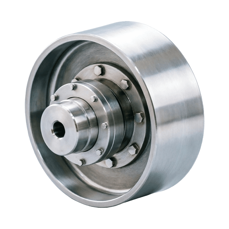
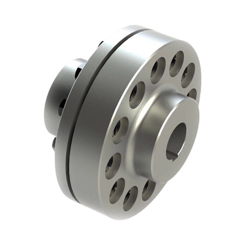
Two quotes land for the same replacement gear coupling: $1,850 from one shop and $2,600 from another. Both promise stan...
READ MORE
Elastic Pin Gear Coupling with Brake Wheel: Integrated Torque Transmission and Reliable Industrial Braking
Admin 2026-08-30Content
- 1 Product Overview
- 2 How the Integrated Structure Works
- 3 Core Product Advantages
- 4 Advantages Compared with Conventional Separate Arrangements
- 5 Manufacturing and Quality Strengths
- 6 Application Areas
- 7 Technical Selection Considerations
- 8 Installation Best Practices
- 9 Maintenance and Inspection
- 10 Safety Considerations
- 11 Customization and Technical Service
- 12 Why Manufacturer Capability Matters
- 13 Purchasing and Project Evaluation Guide
- 14 Frequently Asked Questions
- 14.1 What is an elastic pin gear coupling with brake wheel?
- 14.2 What is the main benefit of integrating the brake wheel?
- 14.3 Does the coupling eliminate the need for a brake actuator?
- 14.4 How do the elastic pins improve operation?
- 14.5 Can the coupling compensate for major misalignment?
- 14.6 What operating temperature range is specified?
- 14.7 Is the product suitable for outdoor equipment?
- 14.8 Where is this coupling commonly used?
- 14.9 What information is needed for product selection?
- 14.10 How should the brake wheel be maintained?
- 14.11 How often should the elastic pins be replaced?
- 14.12 Can the product be customized?
- 14.13 What makes the manufacturer suitable for industrial coupling projects?
- 15 Conclusion
- 16 References
- 17 Product: LZZ(ZLL) Elastic Pin Gear Coupling with Brake Wheel
Modern industrial transmission systems increasingly require equipment that can transmit substantial torque, operate reliably under demanding conditions, and stop safely when required. In many machines, the coupling and braking system are treated as two separate assemblies. Although this arrangement is familiar, it can increase the overall length of the transmission line, consume valuable installation space, add alignment requirements, and complicate maintenance. The LZZ/ZLL elastic pin gear coupling with brake wheel provides an integrated alternative by combining flexible torque transmission and braking control in one coordinated mechanical assembly.
This coupling is based on the established structure of an elastic pin gear coupling. Its distinguishing feature is the brake wheel connected with the coupling body. The integrated arrangement allows the product to transmit power between two shafts while also providing a dedicated rotating surface for a braking mechanism. It is particularly suitable for industrial equipment that experiences frequent starting and stopping, controlled deceleration, emergency braking, or strict space limitations.
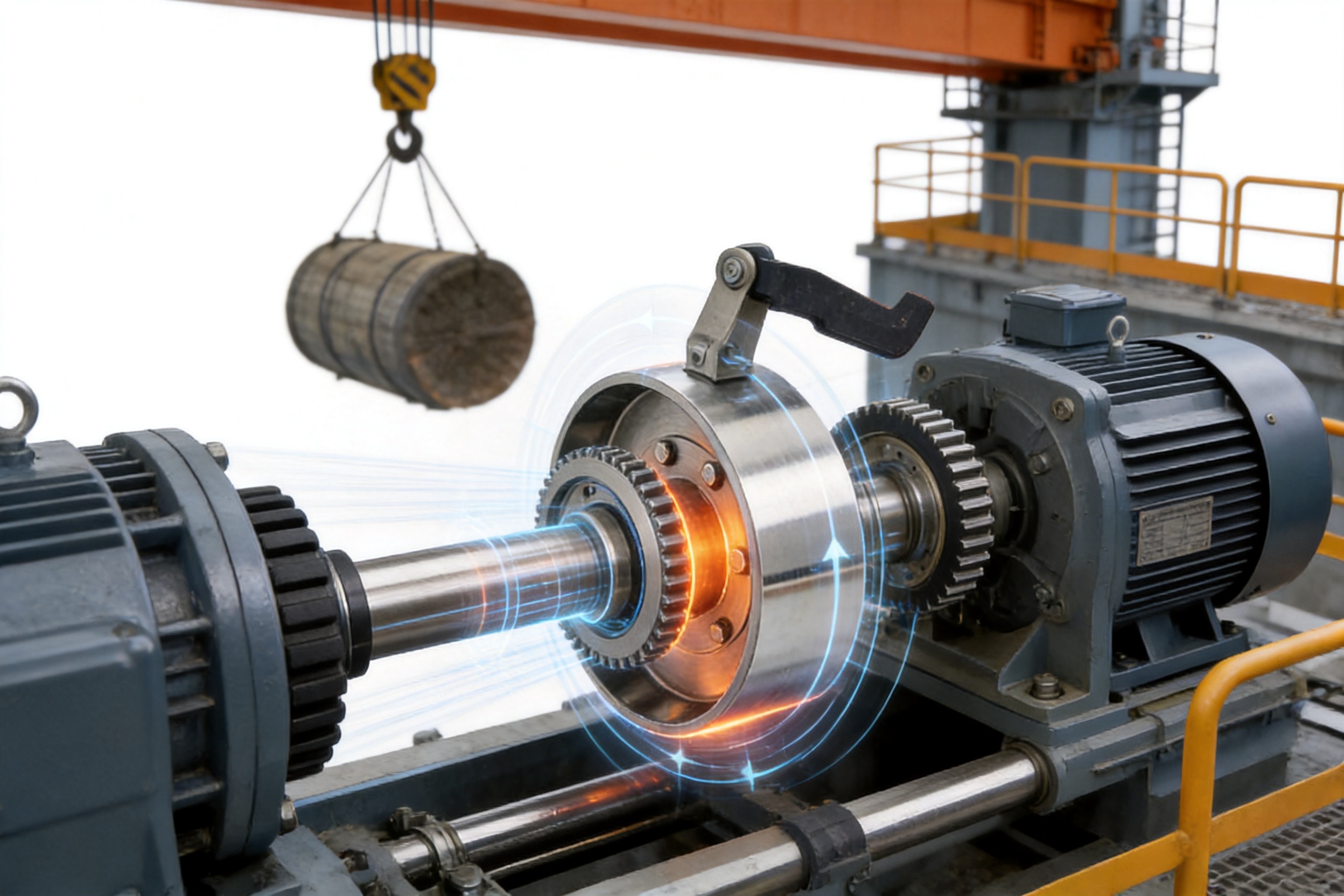
The design combines a toothed outer ring, coupling halves, non-metallic elastic pins, and a specially treated brake wheel. During normal operation, torque passes through the coupling while the elastic pins provide a degree of flexibility and impact absorption. During braking, the brake wheel works with the external brake assembly to slow or stop the rotating system. This coordinated construction offers a practical solution for cranes, hoisting equipment, conveyors, metallurgical machinery, mining systems, construction equipment, and other heavy-duty industrial applications.
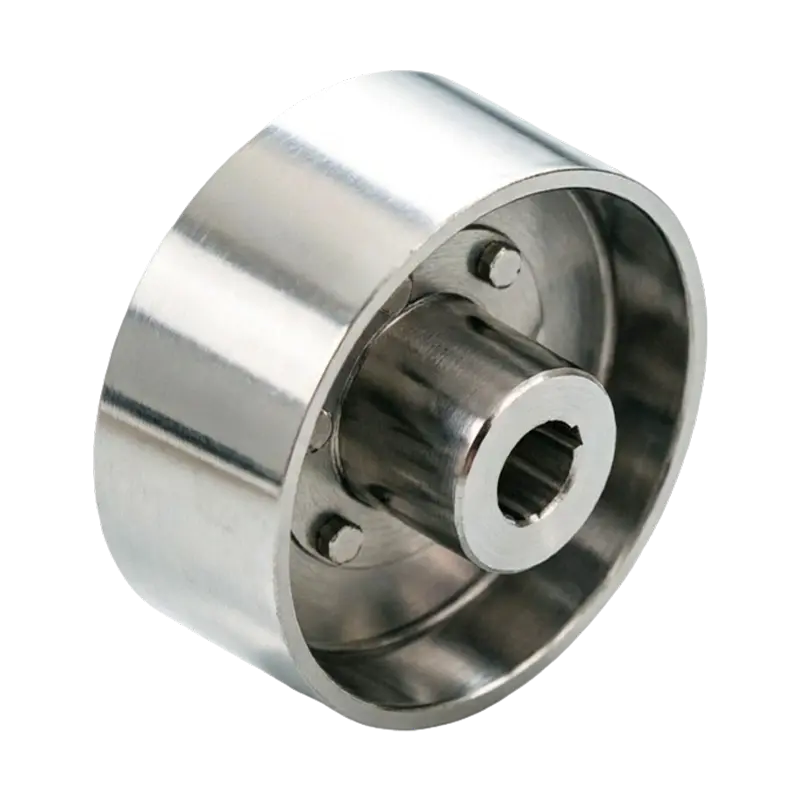
LZZ(ZLL) Elastic Pin Gear Coupling with Brake Wheel
Product Overview
The LZZ/ZLL elastic pin gear coupling with brake wheel is a flexible shaft coupling designed for the connection of two rotating shafts. It accommodates the transmission of rotational torque while offering limited flexibility to help manage small installation errors, vibration, and transient impact loads. The brake wheel is integrated into the coupling structure rather than being installed as a completely independent component elsewhere in the transmission line.
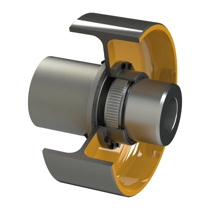
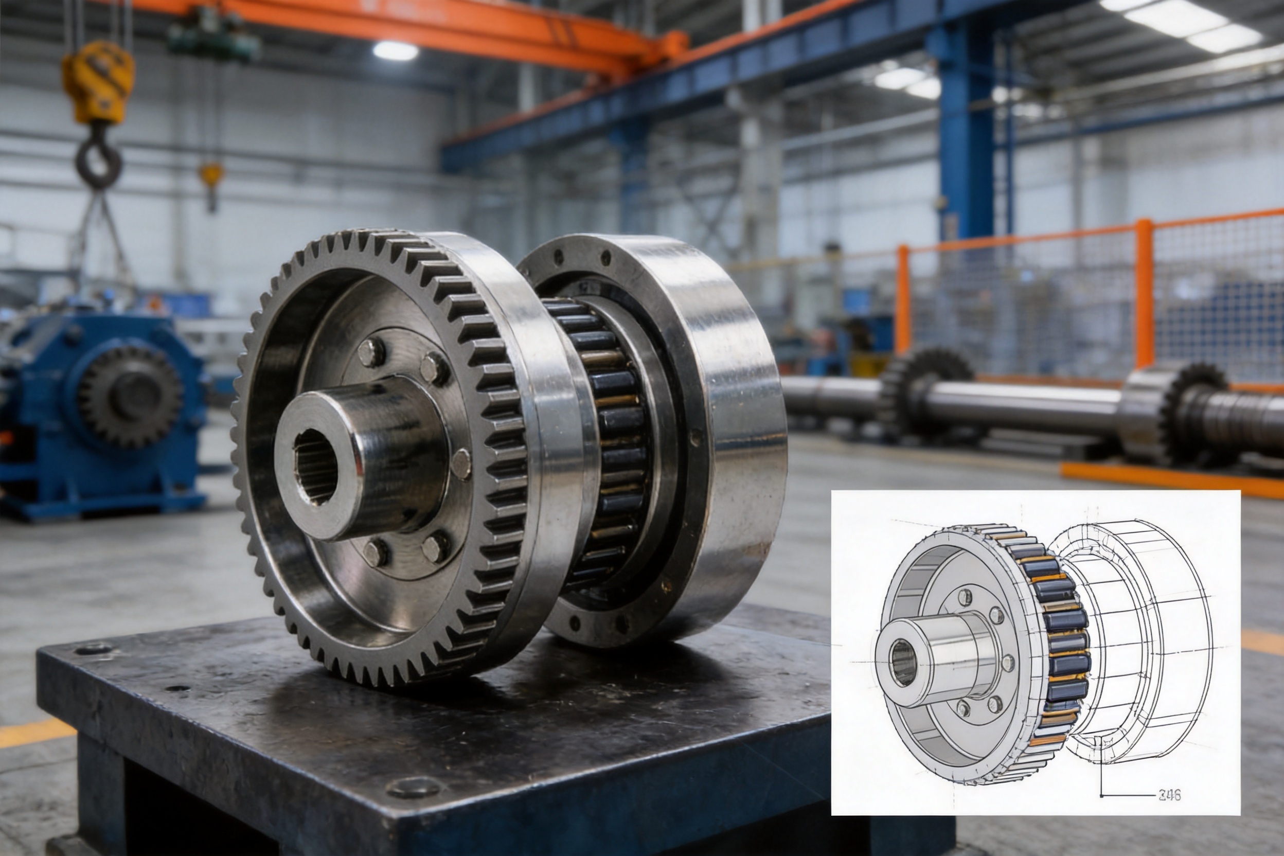
An elastic pin gear coupling generally consists of two coupling halves, a toothed outer ring, and elastic pins positioned in the mating holes between the coupling halves and the outer ring. The gear-like engagement enables torque transmission, while the pins create a flexible connection. In the brake-wheel version, the coupling body is additionally configured with a brake wheel that can interact with a brake shoe, caliper, or other suitable braking device.
The coupling should be selected according to the shaft diameter, rated torque, peak torque, rotational speed, service factor, brake force, operating temperature, installation arrangement, and applicable equipment standards. Proper selection ensures that the coupling is neither overloaded during normal operation nor exposed to excessive shock during acceleration, deceleration, or emergency stopping.
Unlike a rigid shaft connection, the elastic pin design does not depend entirely on precise metal-to-metal contact for the absorption of every operational disturbance. The non-metallic pins introduce a controlled degree of resilience into the connection. This helps reduce the effect of minor impact loads and supports more stable operation of the connected shafts.
Unlike a conventional coupling installed beside a separate brake disc or brake drum, the integrated configuration can reduce the number of major components in the transmission chain. The result is a more streamlined assembly with fewer interfaces, fewer mounting locations, and a potentially shorter axial arrangement.
How the Integrated Structure Works
Torque Transmission Through the Coupling
When the driving shaft rotates, torque is transferred through the first coupling half, the elastic pins, the toothed outer ring, and the second coupling half before reaching the driven shaft. The precise path of load transfer depends on the detailed construction and fit of the selected model, but the core principle is that the gear-shaped structure distributes the transmitted load around the coupling circumference.
Load distribution around multiple pins and mating holes helps avoid concentrating all torque at a single connection point. The elastic pins also provide a flexible interface between the metallic components. Under normal operating conditions, they transmit torque while allowing limited relative movement between the coupling elements.
This flexibility is valuable in equipment exposed to starting shock, load variation, or repeated acceleration and deceleration. It does not eliminate the need for correct shaft alignment, but it can help the coupling tolerate small deviations that would be more severe in a fully rigid arrangement.
Braking Through the Integrated Brake Wheel
During braking, the brake wheel rotates together with the coupling and the connected shaft. A compatible braking device applies friction to the wheel surface. The friction converts rotational energy into heat and reduces the speed of the transmission system. When the brake is released, the wheel rotates freely with the coupling without interfering with normal torque transmission.
Integrating the brake wheel with the coupling body means that the braking force is applied directly to the rotating transmission element. This can simplify the relationship between the braking point and the shaft connection. It also helps reduce the need for an additional shaft-mounted brake component, provided that the brake capacity and coupling specifications are correctly matched.
Braking performance depends on more than the coupling alone. Brake lining material, brake actuator response, wheel diameter, contact pressure, stopping frequency, rotational speed, load inertia, ambient conditions, and heat dissipation all affect the complete braking system. The coupling provides the brake wheel, while the full machine designer must ensure that the selected brake assembly can safely control the required load.
Role of the Elastic Pins
The non-metallic elastic pins are central to the performance of this coupling type. They are positioned in the corresponding holes between the coupling halves and the toothed outer ring. Their function is to transmit torque while allowing a controlled amount of elastic deformation.
When the machine starts, the pins can absorb part of the initial impact associated with acceleration. During fluctuating operation, they help moderate small changes in torque. When the system experiences minor vibration or shock, the flexible connection can reduce the direct transfer of these disturbances from one shaft to the other.
Elastic pins also influence the maintenance life of the coupling. Because they provide a buffer at the connection points, they can reduce the severity of local impact and delay fatigue-related deterioration. Nevertheless, they remain wear components and should be inspected regularly, especially on equipment that operates continuously, reverses frequently, or carries high starting loads.
Core Product Advantages
Integrated Transmission and Braking
The most significant advantage of the LZZ/ZLL design is its combination of coupling and braking functions. A traditional layout may require a separate flexible coupling, brake wheel, brake drum, mounting hub, and additional shaft space. The integrated product brings important parts of these functions into one coordinated unit.
This design can reduce the axial length of the transmission system. In compact machinery, even a small reduction in length can make installation easier and allow more room for guarding, bearings, motors, gearboxes, or maintenance access. A shorter transmission line may also simplify the arrangement of support frames and reduce interference with adjacent components.
Integration can reduce assembly complexity as well. Fewer separate components mean fewer mounting interfaces and fewer opportunities for dimensional mismatch. The machine builder can design the drive and brake around one principal coupling assembly instead of coordinating the locations of two independent shaft-mounted units.
Efficient Use of Installation Space
Industrial equipment is often required to deliver greater output within a limited footprint. Hoisting systems, cranes, conveyors, and production lines may have strict restrictions on shaft spacing and equipment width. The brake-wheel coupling is well suited to these conditions because it combines two functions without requiring a completely separate brake rotor or drum installation.
The space advantage is especially useful when the drive shaft is positioned close to a gearbox, bearing housing, or machine frame. A compact coupling arrangement can provide greater flexibility in the placement of these components. It may also simplify the layout of protective guards, which must be designed to prevent accidental contact with rotating components.
Flexible Impact Absorption
The elastic pin structure provides a practical balance between torque capacity and flexibility. Rigid couplings can transmit torque directly, but they may also transfer vibration and shock with little attenuation. The elastic pin arrangement offers a degree of cushioning during transient events.
This characteristic is valuable in applications where the load is not perfectly uniform. Cranes and hoists, for example, may experience sudden changes as a load is lifted, lowered, positioned, or stopped. Conveyors may undergo starting resistance caused by material accumulation. Mining and construction equipment can encounter fluctuating resistance and impact. The flexible pins help moderate these operational changes.
The coupling is not intended to compensate for large shaft misalignment or poor installation. Instead, its flexibility should be understood as a designed operating feature that supports stable transmission under small and expected deviations.
Responsive and Durable Brake Wheel Surface
The brake wheel surface receives specialized hardening treatment to improve hardness and wear resistance. A durable working surface is essential because the brake wheel is repeatedly exposed to friction, pressure, heat, and possible surface contamination.
Improved surface hardness can help resist scoring, localized wear, and deformation when the brake is applied frequently. A stable wheel surface also supports more predictable contact with the braking element. This contributes to smooth braking response and helps the brake system react promptly when deceleration is required.
The brake wheel should still be protected from excessive contamination, oil, unauthorized grinding, and unsuitable brake lining materials. Surface treatment improves durability, but it does not remove the need for correct brake adjustment and scheduled inspection.
Wide Operating Temperature Range
The stated operating temperature range is from −20°C to +70°C. This range supports use in many indoor and outdoor industrial environments, including facilities where seasonal temperature changes, humidity, and weather exposure are unavoidable.
Weather resistance is particularly important for outdoor cranes, material-handling equipment, construction machinery, and industrial transport systems. The coupling can provide stable service in changing conditions when the product is correctly selected, installed, lubricated where required, and protected from abnormal chemical exposure or direct environmental damage.
Temperature affects both metallic components and elastic materials. At low temperatures, some elastomeric materials may become less flexible. At high temperatures, material aging can accelerate. For this reason, the operating range should be considered together with actual duty cycle, heat generated by braking, ambient ventilation, and the temperature of nearby equipment.
Advantages Compared with Conventional Separate Arrangements
| Comparison factor | Integrated elastic pin gear coupling with brake wheel | Separate coupling and brake arrangement |
| System layout | Transmission and braking functions are coordinated in one principal assembly | Coupling, brake wheel, hub, and mounting components are installed separately |
| Axial space | Potentially shorter transmission line and more compact installation | Requires additional shaft length and mounting clearance |
| Assembly complexity | Fewer major interfaces to position and align | More components and mounting locations require coordination |
| Torque flexibility | Elastic pins provide buffering for minor impact and vibration | Performance depends on the selected coupling and separate brake arrangement |
| Braking response | Brake wheel is directly associated with the rotating coupling body | Response depends on the position and connection of the separate braking component |
| Maintenance focus | Inspection is concentrated around the coupling, pins, wheel, and brake interface | Coupling and brake assemblies require separate inspection and coordination |
| Design suitability | Useful for compact, frequently cycled, and integrated drive systems | Useful where independent component selection or maximum modularity is required |
The table illustrates general design differences rather than replacing application-specific engineering calculations. A separate coupling and brake may remain preferable when a machine requires unusual braking capacity, independent brake positioning, or highly specialized maintenance access. The integrated product offers its greatest value when compactness, simplified construction, and coordinated operation are priorities.
Compared with a basic rigid coupling, the elastic pin gear configuration provides greater tolerance for small operational disturbances. Compared with an ordinary elastic coupling without a brake wheel, it adds an important safety and control function. Compared with a separate brake-wheel solution, it can reduce the number of components and simplify the overall transmission architecture.
Manufacturing and Quality Strengths
Integrated Design and Production Capability
Zhenjiang Orienthold Machinery Co., Ltd. specializes in the production of couplings and papermaking machinery. Its business model integrates product design, manufacturing, inspection, and service. This combination is important for industrial coupling production because coupling performance depends on the relationship between geometry, material selection, heat treatment, elastic components, machining accuracy, and assembly quality.
In-house or closely controlled design and production processes allow the manufacturer to consider the complete working condition rather than treating the brake wheel, coupling body, and elastic pins as unrelated products. This supports more consistent product development and helps ensure that the final assembly reflects the intended load path and operating requirements.
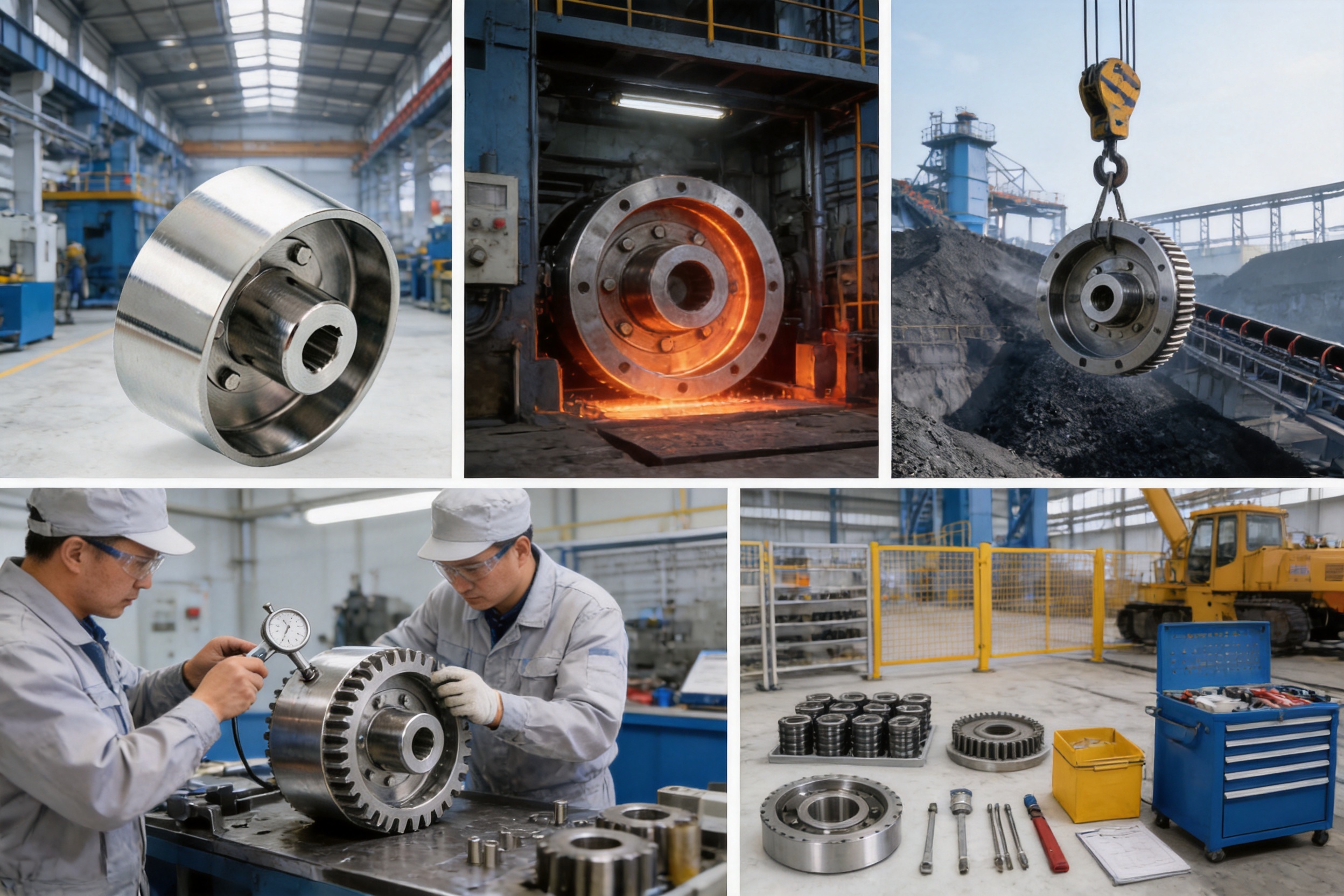
The company serves transportation, metallurgy, chemical engineering, mining, construction, and hoisting industries. These sectors require different combinations of torque, speed, environmental resistance, braking frequency, and maintenance access. Experience across multiple industries helps the manufacturer understand how coupling designs perform under diverse industrial conditions.
Advanced Equipment and Testing Methods
Reliable coupling production requires more than basic machining. The manufacturer reports advanced equipment and comprehensive testing methods, supported by a strict quality supervision system. These capabilities help control the dimensional accuracy, surface condition, assembly quality, and functional consistency of the coupling.
Important manufacturing controls may include inspection of shaft bores, keyways, bolt or pin holes, tooth geometry, brake-wheel dimensions, surface finish, concentricity, and runout. The exact inspection plan depends on the product specification and applicable standard, but each of these characteristics can influence coupling life and braking stability.
Dimensional control is especially important for the brake wheel. Excessive runout can create uneven brake contact, vibration, noise, localized wear, and fluctuating braking force. Accurate machining and inspection help the wheel rotate consistently and maintain a stable relationship with the braking device.
The elastic pin holes also require appropriate dimensional control. If the fit is too tight, assembly may be difficult and unwanted stress may be introduced. If the fit is too loose, impact and backlash may increase. Controlled hole geometry and proper assembly practices help the pins perform their intended buffering and torque-transmission function.
Specialized Surface Treatment
The brake wheel receives specialized hardening treatment to improve resistance to wear. Heat treatment is a critical production stage because it changes the mechanical properties of the working surface. The process must be controlled to achieve the required hardness without creating excessive distortion, cracking, or undesirable internal stress.
After treatment, inspection of the working surface and critical dimensions is important. A high-hardness surface alone is not sufficient if the wheel has unacceptable runout or if the treatment causes dimensional changes that affect assembly. The manufacturer’s production and testing capabilities support the coordination of these requirements.
Surface treatment also demonstrates the product’s application-oriented design. The brake wheel is not simply a structural flange added to a coupling. It is a working friction component that must withstand repeated contact and thermal cycling. Treating the surface specifically for this duty improves its suitability for frequent start-stop operation.
National Standards and Quality Supervision
The company states that its products comply with national standards and that it operates under a strict quality supervision system. Compliance with applicable standards provides a basis for consistent design, production, inspection, and documentation. Buyers should confirm the exact standard, model designation, test requirements, and documentation applicable to their order.
A disciplined quality system helps reduce variation between production batches. It also supports traceability, inspection records, process control, and corrective action when a nonconformity is identified. For industrial couplings, these controls are particularly valuable because the products are often installed in systems where an unexpected failure can interrupt production or create a safety hazard.
Quality supervision should extend from incoming materials through machining, heat treatment, component inspection, assembly, final testing, packaging, and shipment. The manufacturer’s one-stop service approach allows technical communication to continue through these stages, helping customers clarify operating conditions before production and receive maintenance support after delivery.
Application Areas
Cranes and Hoisting Equipment
Cranes and hoists are among the most appropriate applications for an elastic pin gear coupling with brake wheel. These systems frequently start, stop, hold, lower, and reposition loads. The brake must respond reliably, while the coupling must transmit torque through repeated cycles and occasional load fluctuations.
The integrated design can reduce the length of the hoisting transmission assembly. This is useful in crane machinery rooms and compact lifting mechanisms where motor, reducer, drum, bearing, and brake positions must be carefully coordinated. The elastic pins can also help moderate starting impact when the hoisting drive accelerates under load.
Selection must account for suspended load, lifting class, duty cycle, emergency stopping requirements, brake torque, drum speed, and the consequences of load movement after brake release. The coupling should be installed with appropriate guarding and should never be treated as a substitute for a complete hoisting safety system.
Conveyors
Conveyor drives can experience high starting resistance, material accumulation, and repeated operating cycles. In mining, ports, cement plants, warehouses, and production facilities, conveyors may also require controlled stopping to prevent material spillage or protect downstream machinery.
The flexible connection of the elastic pins helps absorb small torsional disturbances during startup and changing load conditions. The integrated brake wheel provides a convenient point for stopping the drive when the conveyor must be held in position or brought to a controlled stop.
For long conveyors, the designer should evaluate inertia, belt tension, stopping distance, braking heat, and the possibility of reverse movement. The coupling and brake assembly must be selected as part of the complete drive system rather than according to motor power alone.
Metallurgical Equipment
Metallurgical machinery often operates under high loads, variable temperatures, dust, vibration, and frequent production cycles. Rolling mills, material-feeding systems, transfer devices, and auxiliary drives may require a combination of flexible torque transmission and rapid control of rotating components.
The product’s treated brake wheel and temperature capability support industrial use in changing environmental conditions. However, direct exposure to radiant heat, molten material, aggressive scale, or corrosive chemicals should be evaluated carefully. Additional shielding or cooling may be necessary in severe areas.
The manufacturer’s experience in metallurgy allows customers to communicate application conditions such as shock load, cycle frequency, ambient contamination, and maintenance limitations. These details help determine the appropriate coupling size and material or protection requirements.
Mining and Construction Machinery
Mining and construction equipment often operates with fluctuating loads and challenging environments. Crushers, feeders, winches, hoists, conveyors, and lifting mechanisms may be exposed to dust, vibration, impact, moisture, and uneven operating cycles.
The elastic pin design is advantageous where a flexible connection can help moderate sudden torque changes. The integrated brake wheel is useful where machinery must be stopped quickly or held safely during adjustment and maintenance. The compact arrangement can also support mobile or space-restricted equipment layouts.
Mining and construction users should pay particular attention to contamination control, protective guards, inspection intervals, and the condition of elastic pins. Dust and abrasive particles can accelerate wear on exposed surfaces and may affect brake friction if they enter the braking interface.
Transportation and General Industrial Drives
Transportation machinery and general industrial drive systems may require frequent speed changes and controlled stopping. The coupling can be adapted to equipment where the motor and driven machine must remain connected while a brake is applied at a central rotating location.
Other potential applications include material-handling machinery, packaging systems, industrial doors, process equipment, and auxiliary production drives. Suitability depends on the torque and speed requirements, brake duty, shaft arrangement, environmental conditions, and applicable machine safety provisions.
Technical Selection Considerations
Rated and Peak Torque
The first selection parameter is torque. The required coupling rating should exceed the continuous operating torque and should also account for starting torque, acceleration, reversing, load impact, and emergency stopping. A service factor is normally applied according to the severity of the application.
Motor nameplate power alone does not provide enough information. Torque is related to power and speed, but the actual machine load may include shock and transient conditions not reflected in the nominal motor rating. Hoisting, crushing, conveying, and reversing applications often require greater consideration of peak torque than smooth, continuously operating drives.
Rotational Speed
Coupling speed affects centrifugal forces, balance requirements, vibration, and brake-wheel performance. The selected model must have a permissible speed suitable for the complete assembly. If the brake wheel has significant mass or an uneven surface, dynamic balance becomes increasingly important as speed rises.
Users should provide the maximum operating speed, not only the normal speed. Overspeed conditions during testing, unloaded operation, or control-system malfunction should be assessed separately. The coupling should not be operated beyond its rated limit.
Brake Capacity
The brake-wheel diameter and surface must be matched with a compatible brake. Required braking torque depends on the rotating inertia, load torque, speed, stopping time, slope or suspended load, and safety requirements. Frequent braking generates heat, and the brake system must dissipate that heat without exceeding permissible temperatures.
Emergency braking is different from normal service braking. An emergency stop may generate higher thermal and mechanical stress. The machine designer should evaluate the number of emergency stops, the interval between stops, brake lining wear, and the possibility of repeated application after a fault.
Shaft and Bore Requirements
Shaft diameters, keyway dimensions, hub length, shaft extension, and fit tolerances must be confirmed before ordering. The coupling should fit the shafts without forcing, excessive clearance, or unauthorized modification.
Keyways and keys must be correctly sized and properly seated. Misaligned keys, burrs, damaged shaft surfaces, and incorrect fits can introduce stress concentrations and runout. Any required special bore, taper, spline, or connection arrangement should be discussed with the manufacturer before production.
Alignment
The elastic pins allow limited flexibility, but they do not correct poor alignment. Angular, parallel, and axial alignment should be checked during installation. Excessive misalignment increases pin deformation, tooth loading, vibration, heat generation, and wear.
Alignment should be checked after the motor, gearbox, and driven machine have reached their final positions. Thermal expansion, foundation movement, bearing clearance, and soft foot can change the alignment after installation. A precision alignment procedure is recommended for important or heavily loaded equipment.
Operating Environment
The product is designed for an operating temperature range of −20°C to +70°C and has strong weather resistance. Even within this range, the application environment should be reviewed for humidity, water spray, dust, abrasive particles, oil, chemicals, salt atmosphere, and ultraviolet exposure.
Where the coupling is installed outdoors, suitable guarding and drainage should be provided. Where corrosive substances are present, material compatibility and protective coatings should be confirmed. If the brake wheel is exposed to oil or grease, braking performance may be reduced and the friction surface may require corrective maintenance.
Installation Best Practices
Before installation, inspect all coupling components and confirm that the delivered model matches the approved drawing or purchase specification. Check the shaft dimensions, keyways, coupling bores, brake-wheel condition, elastic pins, fasteners, and protective parts.
Clean the shaft surfaces and coupling bores. Remove burrs, rust, paint buildup, and foreign material that could affect fit or concentricity. Do not hammer directly on the brake wheel or apply uncontrolled force to the coupling components.
Install the coupling according to the manufacturer’s assembly instructions. Use the specified fit, key, fastener, and tightening procedure. If a component must be heated for installation, temperature control is essential to prevent damage to elastic materials, surface treatments, or nearby components.
Align the connected shafts before final tightening. Verify axial position, angular alignment, parallel offset, and coupling runout. Rotate the assembly manually where possible to confirm that it turns freely and that the brake wheel does not contact the brake mechanism when the brake is released.
Set the brake clearance according to the brake manufacturer’s requirements. Excessive clearance can delay braking response, while insufficient clearance can cause continuous friction, overheating, and premature wear. Confirm that the brake actuator releases completely and that no foreign material is present on the friction surfaces.
After installation, perform a no-load trial run. Observe vibration, unusual noise, brake-wheel runout, pin movement, temperature, and brake release. Gradually introduce the operating load and verify stopping performance under controlled conditions. The first inspection should be scheduled after an initial running period because settling or alignment changes may become visible during early operation.
Maintenance and Inspection
Elastic Pin Inspection
Elastic pins should be inspected for cracking, hardening, deformation, abrasion, loosening, and excessive clearance. Deteriorated pins can increase backlash and impact, reduce torque-transmission stability, and accelerate wear in the mating holes.
Inspection frequency depends on duty cycle and operating conditions. Equipment with frequent starts and stops, reversing, high shock, or heavy loads requires more frequent inspection than a continuously operating smooth drive. Replacement should be carried out with the correct pin type and material rather than with improvised substitutes.
Brake Wheel Inspection
Inspect the brake wheel for scoring, cracks, excessive wear, thermal discoloration, deformation, and contamination. Measure wear where appropriate and compare the results with the permitted limits for the complete brake system.
A rough or uneven wheel surface can lead to unstable braking, noise, vibration, and accelerated lining wear. If machining or resurfacing is considered, the allowable dimensional limits and surface-hardening requirements must be confirmed first. Unauthorized removal of the hardened layer may reduce service life.
Fasteners and Connections
Fasteners should be checked for loosening, corrosion, damaged threads, and signs of fatigue. Coupling bolts, retaining elements, brake-mounting parts, and guards must remain secure throughout operation.
Any abnormal fretting marks, metal dust, or repeated loosening should be investigated rather than simply corrected by retightening. These signs may indicate misalignment, excessive torque, vibration, incorrect fit, or a damaged component.
Lubrication and Cleanliness
Lubrication requirements depend on the specific coupling construction and the manufacturer’s instructions. Where lubrication is required, use the approved lubricant and quantity. Excess lubricant should not be allowed to migrate onto the brake-wheel friction surface.
The coupling and brake area should be kept clean and protected from water accumulation, abrasive dust, and oil contamination. Guards should be inspected to ensure they do not rub against rotating parts and that they remain capable of preventing accidental contact.
Monitoring Operating Symptoms
Changes in vibration, noise, temperature, stopping time, brake response, or starting shock may indicate developing problems. A small change observed early can often be corrected before it becomes a major failure.
Operators should record inspection findings and replacement dates. A maintenance history helps identify wear trends and supports better planning of spare pins, brake linings, and other service parts. For critical equipment, vibration monitoring and temperature measurement can provide additional information.
Safety Considerations
The rotating coupling and brake wheel must be enclosed with a suitable guard whenever personnel could come into contact with them. The guard should be strong enough for the environment, properly secured, and designed to allow inspection without creating unnecessary exposure to moving parts.
Maintenance must be performed only after the machine has been stopped, isolated, locked out, and verified to be free of stored mechanical, electrical, hydraulic, pneumatic, and suspended-load energy. A stopped coupling may still move if the brake is released or if the connected equipment is under load.
Do not rely solely on the brake to support a suspended load during maintenance. Additional mechanical supports or load-retention measures should be used according to the machine’s safety procedures. The brake wheel and brake mechanism should not be modified without an engineering review.
Before returning the equipment to service, confirm that all guards, fasteners, tools, and temporary supports have been removed or correctly installed. Test the brake in a controlled area and confirm that the machine stops as intended.
Customization and Technical Service
Industrial couplings frequently require customization because shaft dimensions, brake arrangements, operating environments, and machine interfaces differ from one project to another. Orienthold Machinery provides design, production, and service capabilities intended to support these requirements.
Customization may involve bore dimensions, keyways, shaft connections, brake-wheel dimensions, material selection, surface treatment, environmental protection, or special inspection documentation. The feasibility of each modification must be confirmed against torque, speed, balance, thermal, and structural requirements.
Customers should provide complete application information when requesting a quotation. Useful data includes motor power, operating speed, shaft diameter, shaft extension, transmitted torque, starting frequency, reversing frequency, load inertia, brake torque, stopping time, ambient temperature, installation orientation, and duty classification.
Clear technical communication at the quotation stage helps prevent later changes. Drawings, dimensional tolerances, inspection requirements, packing details, delivery schedule, and spare-part expectations should be agreed before production begins.
The company also provides one-stop support covering pre-sales consultation, customization, flexible logistics and payment options, and maintenance support. This service model is beneficial for overseas industrial customers that need assistance from product selection through long-term operation.
Why Manufacturer Capability Matters
A coupling is a relatively compact component, but its reliability affects the entire drive system. A dimensional error in a bore, keyway, tooth profile, or brake wheel can lead to vibration or premature wear throughout the machine. Similarly, inadequate control of elastic-pin material can reduce flexibility and shorten service life.
For this reason, buyers should evaluate not only the catalog description but also the manufacturer’s design experience, production resources, inspection capability, and service response. A supplier that understands both couplings and related industrial machinery can better interpret the actual operating conditions.
Orienthold Machinery’s experience in transportation, metallurgy, chemical engineering, mining, construction, and hoisting provides a broad industrial foundation. Its product range includes drum gear couplings, diaphragm couplings, elastic sleeve pin couplings, cross universal couplings, plum elastic couplings, elastomeric pin couplings, elastomeric pin gear couplings, crane drum couplings, and tire couplings.
This product breadth indicates experience with different transmission principles and application requirements. It allows customers to compare alternative coupling solutions when the initial design needs to be reconsidered. A supplier capable of offering multiple coupling types can help identify whether the integrated brake-wheel design, another elastic coupling, or a different shaft-connection arrangement is most appropriate.
The company’s production of papermaking machinery also contributes to its understanding of continuous industrial operation, alignment, rotating equipment, and production-line reliability. Although each application must be assessed independently, this broader machinery background supports practical engineering communication.
Purchasing and Project Evaluation Guide
When evaluating the LZZ/ZLL elastic pin gear coupling with brake wheel, begin with the functional requirement. Determine whether the machine needs a holding brake, service brake, emergency brake, or a combination of these functions. Define how often the brake will operate and how quickly the equipment must stop.
Next, calculate the transmission requirement. Confirm continuous torque, peak torque, speed, direction of rotation, duty cycle, and possible shock loads. If the equipment has a high-inertia load or a long conveyor, stopping conditions may be more demanding than normal running conditions.
Review the installation envelope. Measure available axial length, radial clearance, shaft spacing, motor and gearbox positions, guard dimensions, and access for replacement of elastic pins or brake linings. The integrated structure delivers the greatest benefit when it solves a genuine space or layout requirement.
Evaluate the environment. Confirm whether the temperature falls within −20°C to +70°C and whether the coupling will be exposed to moisture, dust, chemicals, salt, oil, or direct heat. Determine whether additional covers, coatings, seals, or ventilation are required.
Finally, agree on documentation and support. Technical drawings, material information, inspection records, installation instructions, spare-part recommendations, and after-sales contact details can all contribute to reliable project execution.
Frequently Asked Questions
What is an elastic pin gear coupling with brake wheel?
It is a shaft coupling that transmits torque through a gear-type outer ring and elastic pins while incorporating a brake wheel into the coupling body. The coupling connects two shafts and the brake wheel provides a rotating friction surface for a compatible brake mechanism.
What is the main benefit of integrating the brake wheel?
The main benefit is the combination of torque transmission and braking in one coordinated assembly. This can reduce axial space, simplify the transmission layout, decrease the number of major mounting interfaces, and support compact machine design.
Does the coupling eliminate the need for a brake actuator?
No. The product provides the brake wheel, but a compatible brake actuator, brake shoe, caliper, or other braking device is still required. The complete brake system must be selected according to the required braking torque, stopping time, heat load, and safety conditions.
How do the elastic pins improve operation?
The non-metallic elastic pins transmit torque while providing a degree of flexible buffering. They can help absorb minor impact loads, reduce the direct transfer of vibration, stabilize the connection, and delay fatigue at the coupling interfaces.
Can the coupling compensate for major misalignment?
No. It is designed to accommodate limited and controlled flexibility, not major installation errors. Excessive angular, parallel, or axial misalignment can cause rapid wear, vibration, overheating, and failure. Accurate alignment remains essential.
What operating temperature range is specified?
The stated operating temperature range is −20°C to +70°C. Applications outside this range, or applications with high brake-generated heat, should be reviewed with the manufacturer before selection.
Is the product suitable for outdoor equipment?
It has strong weather resistance and can be used in many outdoor or humid industrial environments within the specified temperature range. Outdoor installations still require suitable guards, drainage, corrosion protection, and regular inspection.
Where is this coupling commonly used?
Typical applications include cranes, hoists, conveyors, metallurgical equipment, mining machinery, construction equipment, transportation systems, and other industrial drives requiring frequent start-stop operation or controlled braking.
What information is needed for product selection?
Important information includes shaft diameters, bore and keyway requirements, motor power, operating speed, torque, peak load, duty cycle, brake torque, stopping time, ambient temperature, installation orientation, and environmental conditions.
How should the brake wheel be maintained?
Inspect it for scoring, cracks, deformation, excessive wear, thermal discoloration, and oil or dust contamination. The braking surface should remain clean and should be measured against the permitted limits of the complete brake system.
How often should the elastic pins be replaced?
There is no universal replacement interval because service life depends on load, speed, shock, temperature, alignment, and operating frequency. Pins should be inspected regularly and replaced when cracking, hardening, deformation, looseness, or excessive clearance is observed.
Can the product be customized?
Customization may be available for bores, keyways, dimensions, materials, surface treatment, and special application requirements. Every modification should be reviewed against torque, speed, balance, braking, and manufacturing constraints.
What makes the manufacturer suitable for industrial coupling projects?
The manufacturer integrates design, production, inspection, and service; uses advanced equipment and comprehensive testing methods; operates a strict quality supervision system; and serves industries such as transportation, metallurgy, chemical engineering, mining, construction, and hoisting.
Conclusion
The LZZ/ZLL elastic pin gear coupling with brake wheel is designed for industrial transmission systems that require both reliable torque transfer and effective braking control. Its integrated structure combines the flexible characteristics of elastic pin gear coupling technology with the practical function of a hardened brake wheel.
Its principal advantages include high integration, reduced axial space, simplified system structure, flexible impact absorption, improved brake-wheel wear resistance, responsive braking capability, and suitability for operation from −20°C to +70°C. These features make it a strong option for cranes, hoists, conveyors, mining equipment, metallurgical machinery, construction systems, and other applications with frequent start-stop requirements.
The product’s performance depends on correct selection, accurate alignment, suitable brake matching, proper installation, and regular maintenance. Equally important is the manufacturing capability behind the product. Orienthold Machinery combines coupling design, production, testing, quality supervision, customization, and technical service to support demanding industrial applications.
For buyers seeking a compact and coordinated alternative to a separate coupling and brake arrangement, this elastic pin gear coupling with brake wheel offers a technically practical solution. By evaluating torque, speed, braking duty, environment, shaft dimensions, and maintenance requirements in advance, users can obtain a coupling configuration that supports safe, stable, and efficient operation over the service life of the equipment.
References
1. Manufacturer-provided product information for the LZZ/ZLL elastic pin gear coupling with brake wheel.
2. Manufacturer-provided technical information regarding elastic pin gear coupling construction and elastomeric pin operation.
3. General engineering principles for flexible shaft coupling selection, alignment, torque transmission, and maintenance.
4. General industrial practices for rotating equipment guarding, brake inspection, stored-energy isolation, and machinery safety.
5. General engineering guidance concerning friction brake capacity, heat generation, wear control, and stopping performance.
Product: LZZ(ZLL) Elastic Pin Gear Coupling with Brake Wheel
PREV: SWC-BH Standard Telescopic Welded Universal Coupling: Structure, Performance, and Industrial ApplicationsNEXT: SWC-CH Long Telescopic Welded Universal Coupling for Demanding Industrial Drives
Be the First to Know
For exclusive deals and latest offers, sign up by entering your email address below.
Related products
News
-
-
Consider a 250 kW crane hoist that begins to vibrate only when the load is lifted. The drum gear coupling is inspected ...
READ MORE -
A maintenance engineer pulls a failed coupling from a pump drive. The elastomer sleeves are cracked, the pin bolts are ...
READ MORE -
Gear Coupling vs. Drum Gear Coupling: The Core Difference The main difference is that "gear coupling" is a broad catego...
READ MORE -
A mill drive rarely fails without warning. It knocks at speed, throws a smear of dark grease around the sleeve flange, ...
READ MORE -
China's coupling industry is at a critical historical juncture of transformation from scale expansion to quality and eff...
READ MORE


ABOUT US
PRODUCTS
INDUSTRIES
CONTACT US
- Phone: +86-18652865511
- Email: sales@ohmach.com
- Address: No.1, Minying Developing Zone, Zhenjiang, Jiangsu, China
Copyright Zhenjiang Orienthold Machinery Co., Ltd. All Rights Reserved.
 Custom Industrial Shaft Coupling Manufacturers