 English
 русский
 Português
 عربى
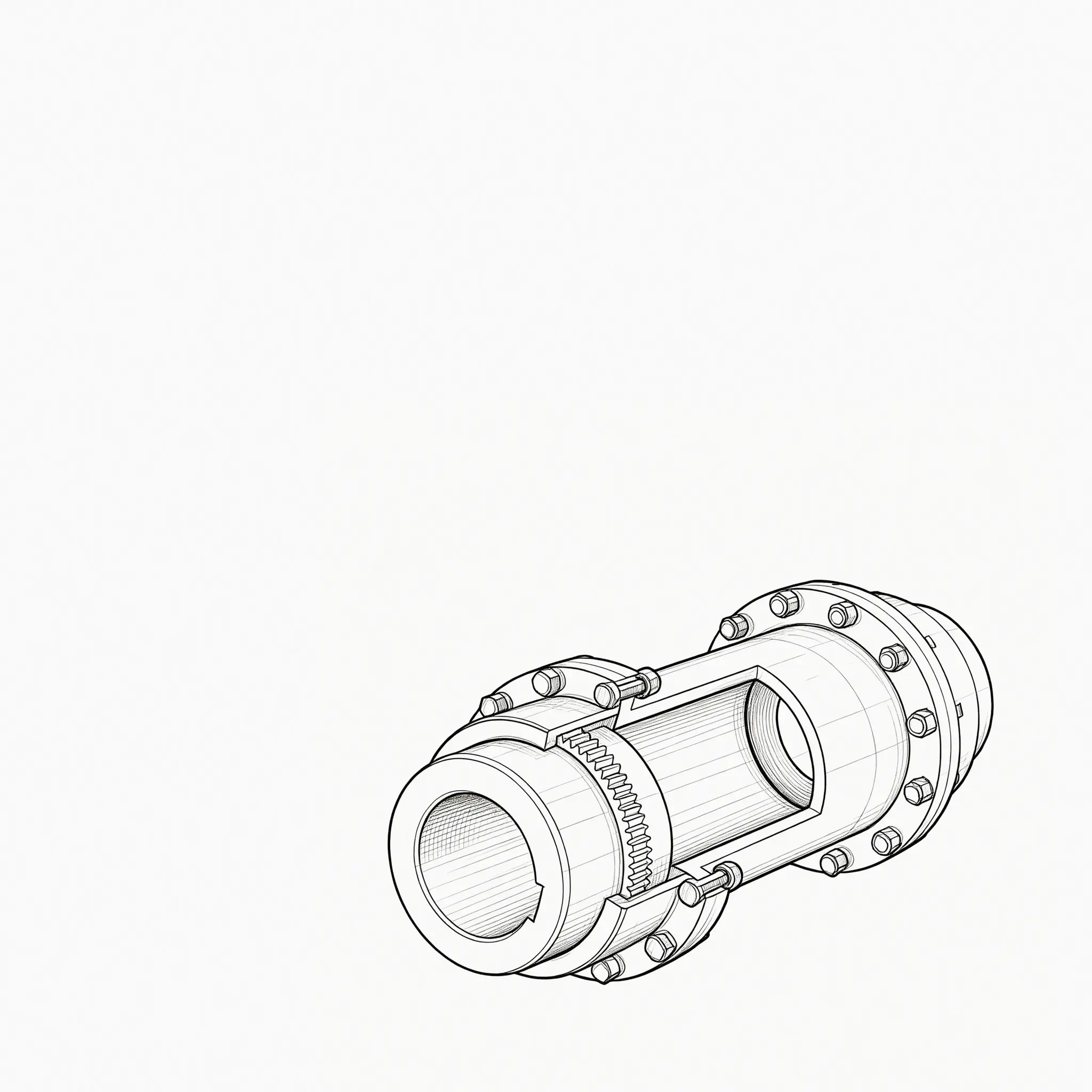
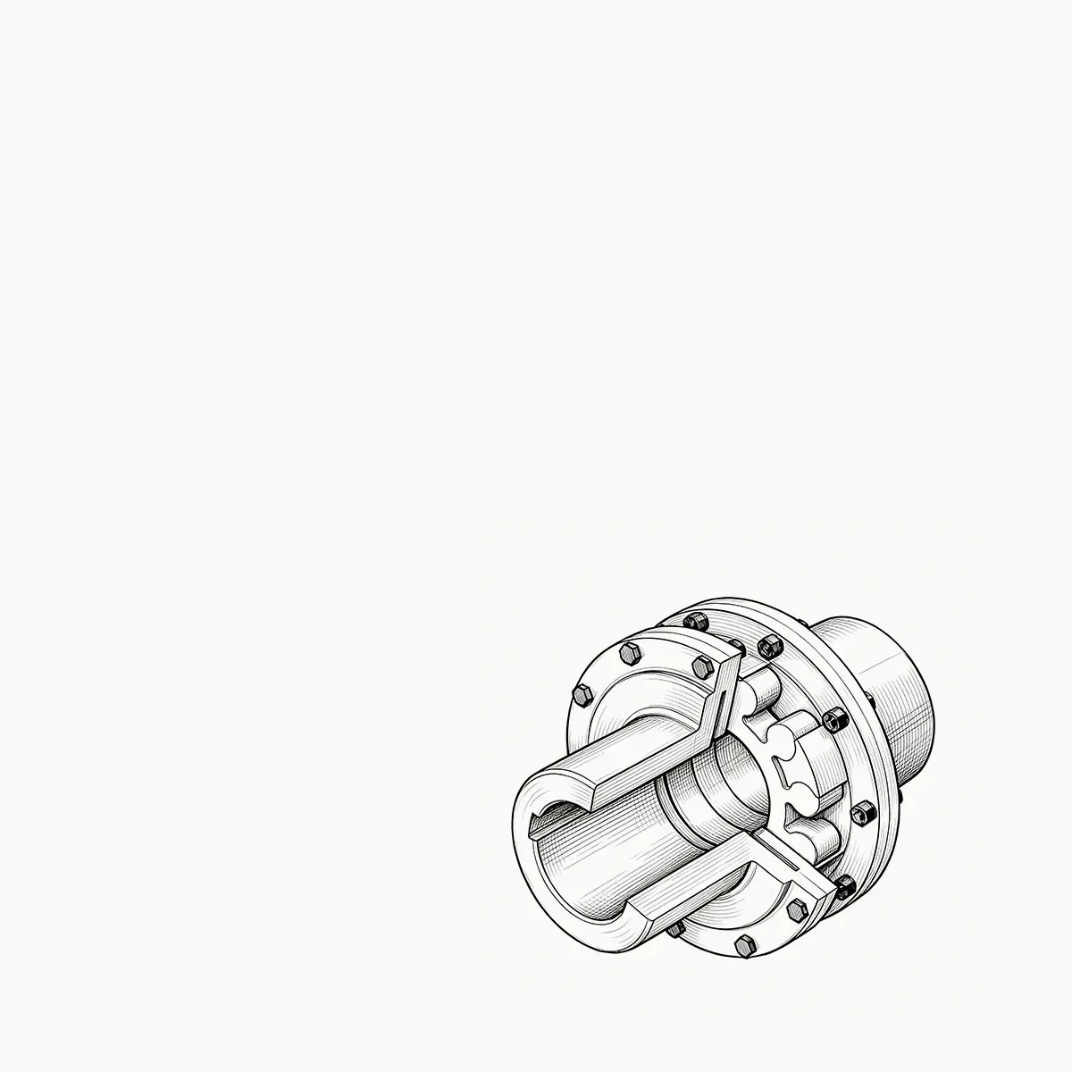
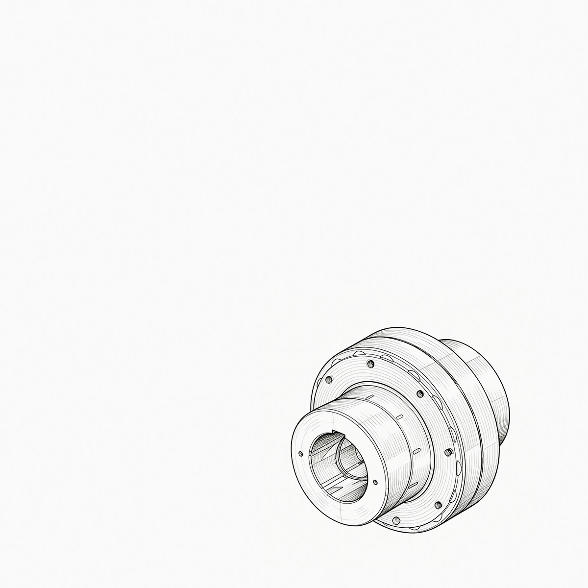
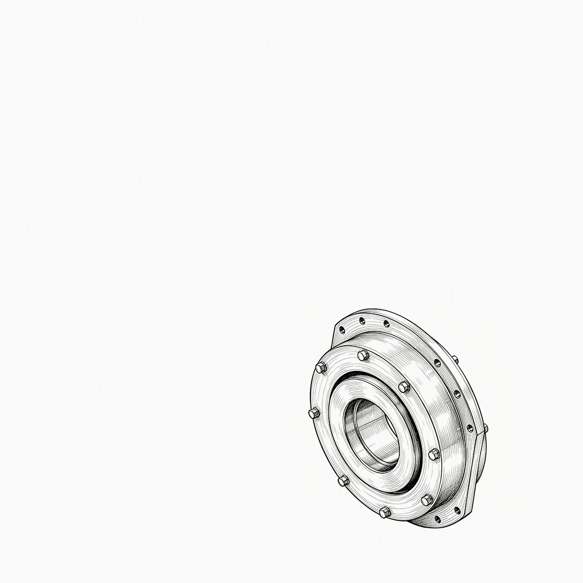

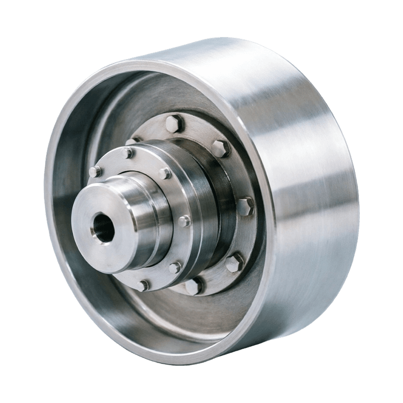
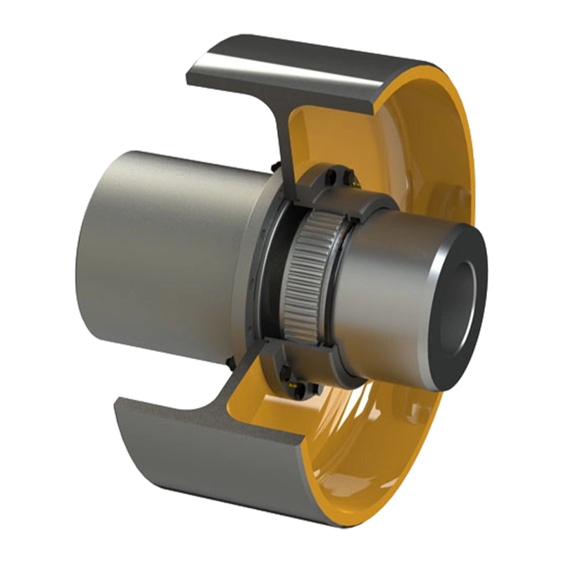
Consider a 250 kW crane hoist that begins to vibrate only when the load is lifted. The drum gear coupling is inspected ...
READ MORE
WG Type Basic Crowned-Gear Coupling: Heavy-Duty Torque Transmission, Misalignment Compensation, and Reliable Industrial Performance
Admin 2026-09-23Content
- 1 Introduction
- 2 Product Overview
- 3 Operating Principle
- 4 Structural Design and Main Components
- 5 Large-Module Gear Design and Load Capacity
- 6 Advantages Compared with Conventional Straight-Tooth Couplings
- 7 Materials and Heat Treatment
- 8 Advanced Manufacturing Process
- 9 Quality Management and Manufacturing Strengths
- 10 Applications in Heavy Industry
- 11 Installation Recommendations
- 12 Maintenance and Service Life
- 13 Selection Guidelines
- 14 Technical Comparison with Alternative Coupling Types
- 15 Frequently Asked Questions
- 15.1 What is a crowned-gear coupling?
- 15.2 What is the main advantage of the WG Type Basic Crowned-Gear Coupling?
- 15.3 What torque range does the coupling cover?
- 15.4 What shaft diameters are available?
- 15.5 How much angular misalignment can the coupling accommodate?
- 15.6 Does the coupling eliminate the need for shaft alignment?
- 15.7 Why are carburizing and quenching used?
- 15.8 Is lubrication required?
- 15.9 Can the coupling be customized?
- 15.10 Which industries commonly use this type of coupling?
- 15.11 What inspection points are most important during maintenance?
- 15.12 How does Orienthold Machinery support customers?
- 16 Why Choose a Specialized Coupling Manufacturer?
- 17 Conclusion
- 18 References
- 19 Product: WG Type Basic Crowned-Gear Coupling
Introduction
Modern industrial drive systems must transmit high torque reliably while operating under vibration, shock loads, contamination, thermal variation, and unavoidable shaft misalignment. In applications such as metallurgy, mining, port machinery, construction equipment, hoisting systems, and heavy manufacturing, the coupling is more than a simple connector between two shafts. It is a critical mechanical element that influences power transmission efficiency, equipment safety, maintenance frequency, and the service life of connected machines.
The WG Type Basic Crowned-Gear Coupling is designed for these demanding operating environments. It combines the high torque capacity of a large-module gear structure with the misalignment compensation capability of a crowned-tooth design. This combination allows the coupling to accommodate radial, axial, and angular deviations while maintaining effective torque transmission and stable operation.
Compared with conventional straight-tooth gear couplings, the WG design provides more flexible tooth engagement. Its crowned tooth profile helps distribute contact more evenly when the connected shafts are not perfectly aligned. This reduces tooth-edge loading, limits localized stress concentration, and improves the coupling’s ability to handle installation tolerances and operating displacement.
The coupling is manufactured from high-strength alloy steel and treated through carburizing and quenching. The resulting hardened surface offers improved wear resistance, while the tougher internal material retains the strength needed for heavy torque transmission and impact loading. Depending on the selected model, the product covers torque ratings from 710 N·m to 3150 kN·m and shaft diameters from 12 mm to 400 mm.
With transmission efficiency of up to 99.7%, a permissible angular misalignment of up to 1°30′ under zero radial displacement, and a carefully engineered sealing structure, the WG Type Basic Crowned-Gear Coupling provides a practical solution for heavy-duty power transmission systems that require both strength and adaptability.
WG Type Basic Crowned-Gear Coupling
Product Overview
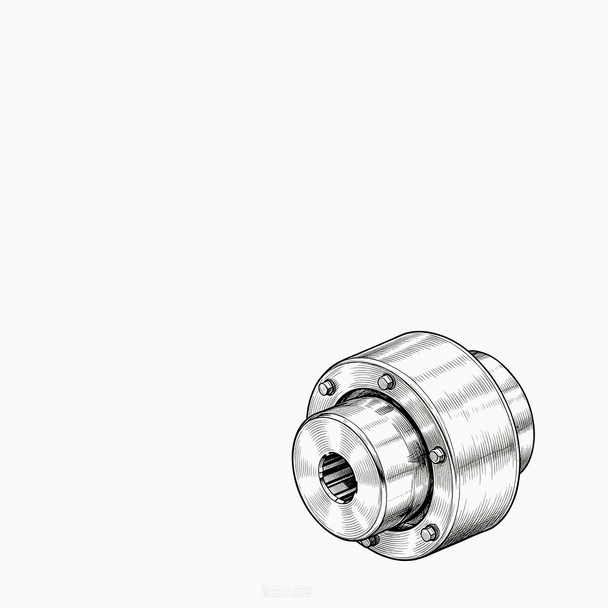
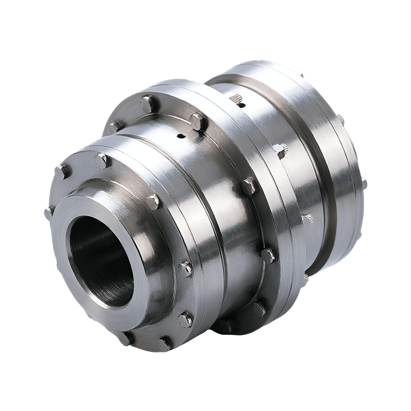
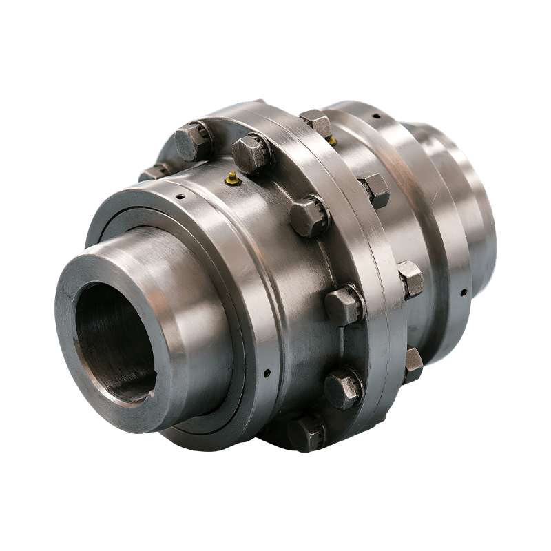
The WG Type Basic Crowned-Gear Coupling is a mechanical shaft coupling used to connect driving and driven shafts. It transfers torque through the engagement of an external gear sleeve and an internal gear ring while allowing a controlled degree of relative movement between the shafts.
In a perfectly aligned drive system, the two shafts share a common centerline. In actual industrial installations, however, alignment may be affected by manufacturing tolerances, foundation settlement, thermal expansion, bearing wear, shaft deflection, installation errors, and dynamic loads. A rigid connection would transfer these deviations directly into the shafts, bearings, and connected equipment. The resulting forces could cause excessive vibration, premature bearing failure, gear damage, or shaft fatigue.
The WG coupling addresses this problem through its crowned gear geometry. Rather than relying on straight tooth flanks that can concentrate the load at the tooth edges during angular displacement, the crowned external gear teeth are shaped with a convex tooth top and an arc-shaped tooth surface. This allows the contact position to shift as the shafts move relative to one another.
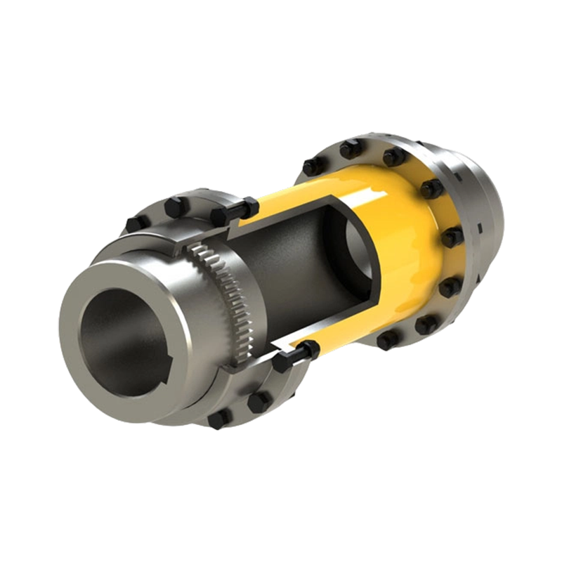
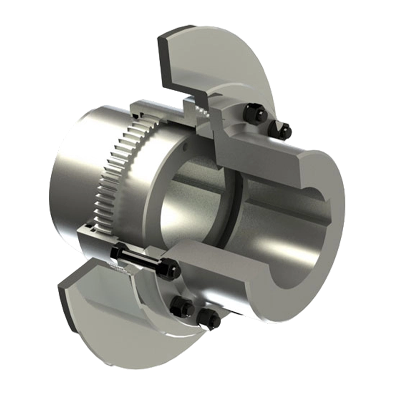
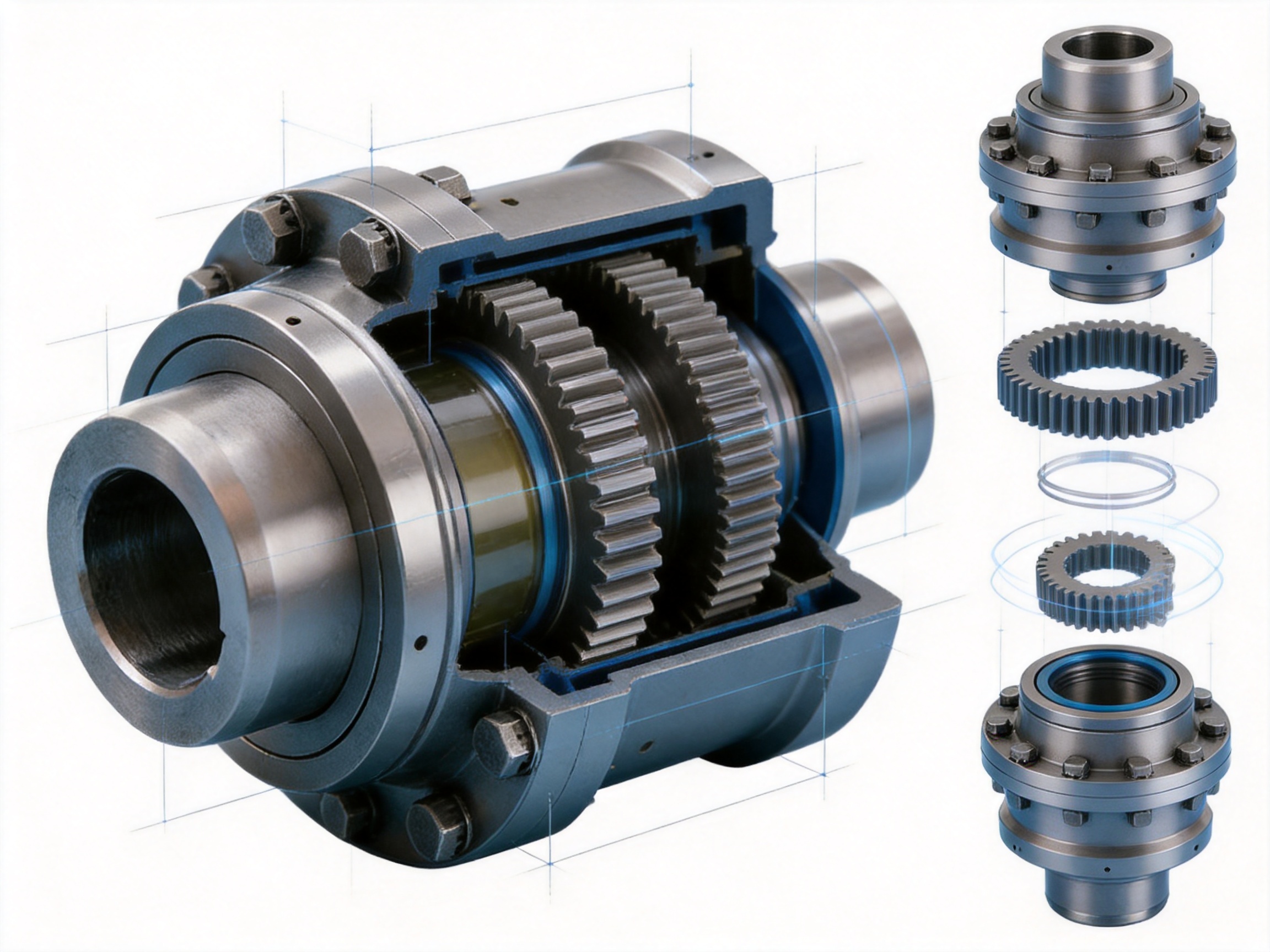
The product is primarily composed of an internal gear ring, an external gear sleeve, end covers, and sealing assemblies. These components work together to form a compact, enclosed torque-transmission unit. Lubricant is retained inside the gear chamber, while the sealing structure helps prevent the entry of dust, moisture, and other contaminants.
The large-module gear design is one of the defining characteristics of this series. A larger module generally allows the coupling to use stronger and more robust gear teeth, increasing its capacity to withstand torque and shock loading. This makes the WG series particularly suitable for large-scale drive systems where standard light-duty couplings may not provide sufficient safety margin.
Operating Principle
Torque enters the coupling through one shaft and is transmitted to the external gear sleeve connected to that shaft. The external teeth engage with the internal teeth of the gear ring connected to the opposite shaft. As the teeth mesh, torque passes through the gear surfaces from the driving member to the driven member.
The gear teeth are designed to remain engaged while permitting controlled angular movement. When the shafts develop an angular, radial, or axial offset, the crowned tooth surfaces allow the contact pattern to adjust. Instead of forcing the tooth edges to carry the load, the geometry helps maintain a more favorable contact condition across the working tooth surfaces.
During operation, the coupling must accommodate several types of displacement. Angular misalignment occurs when the two shaft centerlines intersect at an angle. Radial misalignment occurs when the centerlines are parallel but offset. Axial displacement occurs when one shaft moves along its longitudinal axis. In real equipment, these conditions may appear individually or simultaneously.
The WG coupling is designed to compensate for these movements within the specified limits. Its compensation capability does not eliminate the need for proper shaft alignment. Correct alignment remains essential for safe and efficient operation. However, the coupling provides a valuable tolerance range that reduces the mechanical consequences of unavoidable displacement.
The larger tooth side clearance compared with conventional straight-tooth couplings also contributes to operational flexibility. This clearance allows the tooth pair to adjust its relative position without excessive interference when the connected shafts experience movement. At the same time, the tooth geometry and lubrication system maintain adequate torque-transmission contact.
Under zero radial displacement conditions, the permissible angular misalignment can reach up to 1°30′. This represents an improvement of approximately 50% compared with traditional straight-tooth designs. The specific permissible values for each installation must be confirmed using the relevant product selection data, operating speed, load characteristics, lubrication conditions, and service factor.
Structural Design and Main Components
Internal Gear Ring
The internal gear ring is the component with internal teeth that engage with the external gear sleeve. It is connected to one of the machine shafts through a hub or related mounting arrangement. Its tooth profile must be accurately produced so that the gear pair can transmit torque smoothly and maintain an appropriate contact pattern.
For heavy-duty service, the internal gear ring must resist tooth deformation, wear, impact, and fatigue. The use of high-strength alloy steel and controlled heat treatment helps provide the mechanical properties required for long-term operation. The ring is also designed to work with the coupling’s sealing and lubrication system, forming an enclosed gear chamber.
External Gear Sleeve
The external gear sleeve carries the crowned external teeth. Its tooth profile is the main feature that differentiates this coupling from a traditional straight-tooth gear coupling. The crowned teeth have a convex form that allows the contact location to change as the shafts experience angular or radial displacement.
The sleeve must combine tooth strength with dimensional accuracy. Excessive tooth deviation, surface roughness, or runout could increase vibration and accelerate wear. For this reason, gear cutting, heat treatment, finishing, and inspection must be carefully coordinated during production.
End Covers
The end covers retain lubricant within the coupling and protect the internal gear engagement from the external environment. In industrial facilities, couplings may be exposed to metallic dust, mineral particles, water spray, scale, process residue, or lubricants from nearby equipment. A properly designed enclosure reduces the risk that these contaminants will enter the tooth-meshing area.
The end-cover structure also supports maintenance operations. Depending on the installation design, inspection or lubricant replenishment may be performed without removing the entire coupling from the shaft line. Maintenance procedures should always follow the selected model’s technical documentation.
Sealing Assemblies
Seals are essential to the reliability of a gear coupling. They help prevent lubricant leakage and protect the internal gear surfaces from contamination. Effective sealing contributes to stable lubrication, reduced tooth wear, and longer service life.
The sealing design must also accommodate the relative movement generated by shaft misalignment. A seal that is too rigid may wear rapidly, while a seal with insufficient contact pressure may allow leakage or contamination. The WG coupling’s sealing assemblies are integrated into the overall structure to support operation in demanding industrial environments.
Large-Module Gear Design and Load Capacity
Heavy-duty applications often require high torque transmission within a limited installation envelope. The gear teeth must withstand both steady torque and transient loads caused by starting, stopping, reversing, material impact, or process disturbances. A large-module gear design provides a stronger tooth form and helps increase the load-carrying capability of the coupling.
The WG Type Basic Crowned-Gear Coupling covers a torque range from 710 N·m to 3150 kN·m. This broad range allows the series to serve equipment from medium-sized industrial drives to very large heavy-duty systems. Correct selection depends on rated motor power, operating speed, starting torque, peak torque, load classification, duty cycle, shaft diameter, bore arrangement, and environmental conditions.
Torque capacity should not be considered in isolation. A coupling may experience short-duration overloads that are substantially higher than the normal running torque. Conveyor start-up, crusher blockage, rolling-mill impact, crane acceleration, and hoist braking can all create transient loads. A suitable service factor must therefore be applied during selection.
The large-module structure also improves resistance to tooth bending and surface fatigue. By combining robust dimensions with carburized and quenched surfaces, the coupling is prepared for repeated load cycles. Nevertheless, the operating torque must remain within the manufacturer’s specified rating, and overload protection should be considered where the driven machine can experience severe shock.
| Performance or Design Item | WG Type Basic Crowned-Gear Coupling | Engineering Significance |
|---|---|---|
| Torque range | 710 N·m to 3150 kN·m | Supports medium-duty through very heavy industrial drives |
| Applicable shaft diameter | 12 mm to 400 mm | Provides selection flexibility for different shaft sizes |
| Maximum stated angular misalignment | Up to 1°30′ under zero radial displacement | Improves tolerance to shaft angle deviation |
| Transmission efficiency | Up to 99.7% | Limits mechanical power loss during operation |
| Tooth configuration | Crowned external gear teeth with larger module design | Improves load distribution and torque capacity |
| Material and treatment | High-strength alloy steel with carburizing and quenching | Combines surface wear resistance with internal toughness |
| Protection arrangement | End covers and sealing assemblies | Helps retain lubricant and reduce contamination |
Advantages Compared with Conventional Straight-Tooth Couplings
Improved Misalignment Compensation
The most important advantage of a crowned gear coupling is its ability to accommodate angular misalignment more effectively than a conventional straight-tooth design. With straight teeth, angular displacement can cause contact to migrate toward the tooth edges. This reduces the effective contact area and creates localized stress.
The crowned tooth surface provides a smoother transition in the contact pattern. As the shafts move, the tooth surfaces can maintain a more favorable engagement condition. This reduces the likelihood of edge loading and supports more uniform force distribution across the engaged teeth.
Reduced Localized Stress
Localized stress is a major contributor to pitting, scoring, plastic deformation, and tooth fracture. When the load is concentrated in a small area, the tooth surface may exceed its allowable contact stress even though the average torque appears acceptable.
The WG design helps reduce this risk by allowing the contact position to adjust in response to shaft displacement. The result is a more balanced load path and less severe stress concentration during normal misalignment conditions.
Higher Heavy-Duty Torque Capability
The larger module gear structure provides a stronger solution for high-torque service than many standard compact gear couplings. This is particularly valuable in equipment where torque peaks and impact loads are common.
Applications such as metal-processing machinery, mine conveyors, crushers, hoists, port cranes, and large construction equipment often require couplings with a substantial safety margin. The WG series is engineered for this type of service and can be selected across a wide range of torque and shaft dimensions.
Improved Adaptability to Installation Errors
Even when installation procedures are carefully controlled, shaft alignment errors may occur because of foundation tolerances, thermal movement, bearing seating, or coupling replacement conditions. A coupling with useful misalignment compensation can reduce the effect of these practical installation challenges.
This does not mean that alignment can be neglected. Instead, the crowned gear design provides additional operating tolerance and reduces the sensitivity of the drive system to minor deviations. This can contribute to more stable operation and lower maintenance demand.
Low Power Loss
With transmission efficiency of up to 99.7%, the WG coupling is designed to transfer power with minimal loss. Efficient gear engagement reduces unnecessary energy consumption and limits heat generation in the coupling.
Efficiency is especially important in continuously operating equipment. Even a small reduction in mechanical loss can produce meaningful energy savings over long operating periods. Stable tooth engagement also helps reduce vibration and noise compared with a poorly aligned or excessively worn coupling.
Better Performance in Harsh Environments
Heavy industry frequently exposes mechanical components to dust, moisture, scale, abrasive particles, and temperature changes. The enclosed construction and sealing assemblies of the WG coupling help protect the gear surfaces and retain lubricant.
When combined with correct maintenance, the sealing structure can help reduce contamination-related wear. This is an important advantage over exposed or inadequately protected transmission components used in dusty or wet operating areas.
Materials and Heat Treatment
Material selection is central to the performance of a heavy-duty gear coupling. The components must withstand repeated torque cycles, contact stress, bending stress, impact, and environmental exposure. The WG Type Basic Crowned-Gear Coupling uses high-strength alloy steel to meet these requirements.
Alloy steel provides a suitable foundation for components that require both strength and toughness. The alloy composition supports hardening response and helps the material maintain structural integrity under heavy loading. The final properties depend on the specific steel grade, component geometry, heat-treatment parameters, and quality-control procedures.
Carburizing is used to increase the carbon content at the surface of the gear components. This creates a hardened outer layer after quenching while allowing the internal core to retain greater toughness. The hardened surface resists abrasive wear, adhesive wear, and contact fatigue, while the tougher core helps absorb impact and resist fracture.
Quenching transforms the carburized surface into a high-hardness structure. The process must be controlled carefully because excessive distortion, residual stress, or uneven hardness could affect gear accuracy and service life. Appropriate process control, inspection, and subsequent finishing are essential to achieve the desired performance.
The combination of a hard surface and tough core is particularly appropriate for crowned gear couplings. The tooth surface experiences repeated sliding and rolling contact, while the body of the component must carry torque and respond to shock loads. A balanced material structure helps the coupling perform under both conditions.
Advanced Manufacturing Process
Engineering and Product Design
Manufacturing begins with engineering analysis of the coupling geometry, torque rating, shaft dimensions, tooth engagement, sealing arrangement, and operating conditions. The design process must account for static torque, dynamic loading, permissible misalignment, rotational speed, lubrication, and installation requirements.
For heavy-duty couplings, the design cannot rely only on nominal torque. The engineering team must consider service factors, fatigue cycles, transient overloads, thermal expansion, shaft deflection, and the influence of connected equipment. A coupling that is suitable for a continuously running fan may not be suitable for a crane hoist or a crusher with severe impact loads.
Precision Forging or Material Preparation
High-quality raw material preparation provides the basis for reliable components. Depending on the component design and production route, steel may be supplied as forged blanks or other controlled forms. Forging can refine the grain structure and improve the mechanical integrity of parts that will carry high loads.
Material certificates, chemical composition, hardness, dimensional condition, and internal quality should be reviewed as part of incoming inspection. Proper material traceability allows production personnel to identify the source and processing history of each major component.
CNC Machining
CNC machining is used to produce hubs, sleeves, covers, bores, shoulders, mounting surfaces, and other critical dimensions. Controlled machining improves repeatability and helps maintain the concentricity required for smooth rotation.
Machining accuracy is important because errors in bore alignment, face runout, or tooth-support geometry can increase vibration and impose additional loads on the connected shafts. CNC equipment allows the manufacturer to establish repeatable programs and maintain consistent dimensional relationships between the various coupling elements.
Gear Cutting and Tooth Formation
The external crowned teeth and internal gear teeth must be produced with accurate geometry. Tooth profile, pitch, flank accuracy, root form, runout, and surface finish all influence torque transmission and service life.
Special attention is required for the crowned profile. The crown must be controlled within the intended design parameters. If the curvature is insufficient, misalignment compensation may be reduced. If it is excessive or inconsistent, contact may become uneven and the load capacity may be affected.
Gear cutting is followed by inspection and, where necessary, finishing operations. The purpose is to ensure that the completed teeth provide smooth engagement, appropriate clearance, and a stable contact pattern throughout the rated operating range.
Carburizing and Quenching
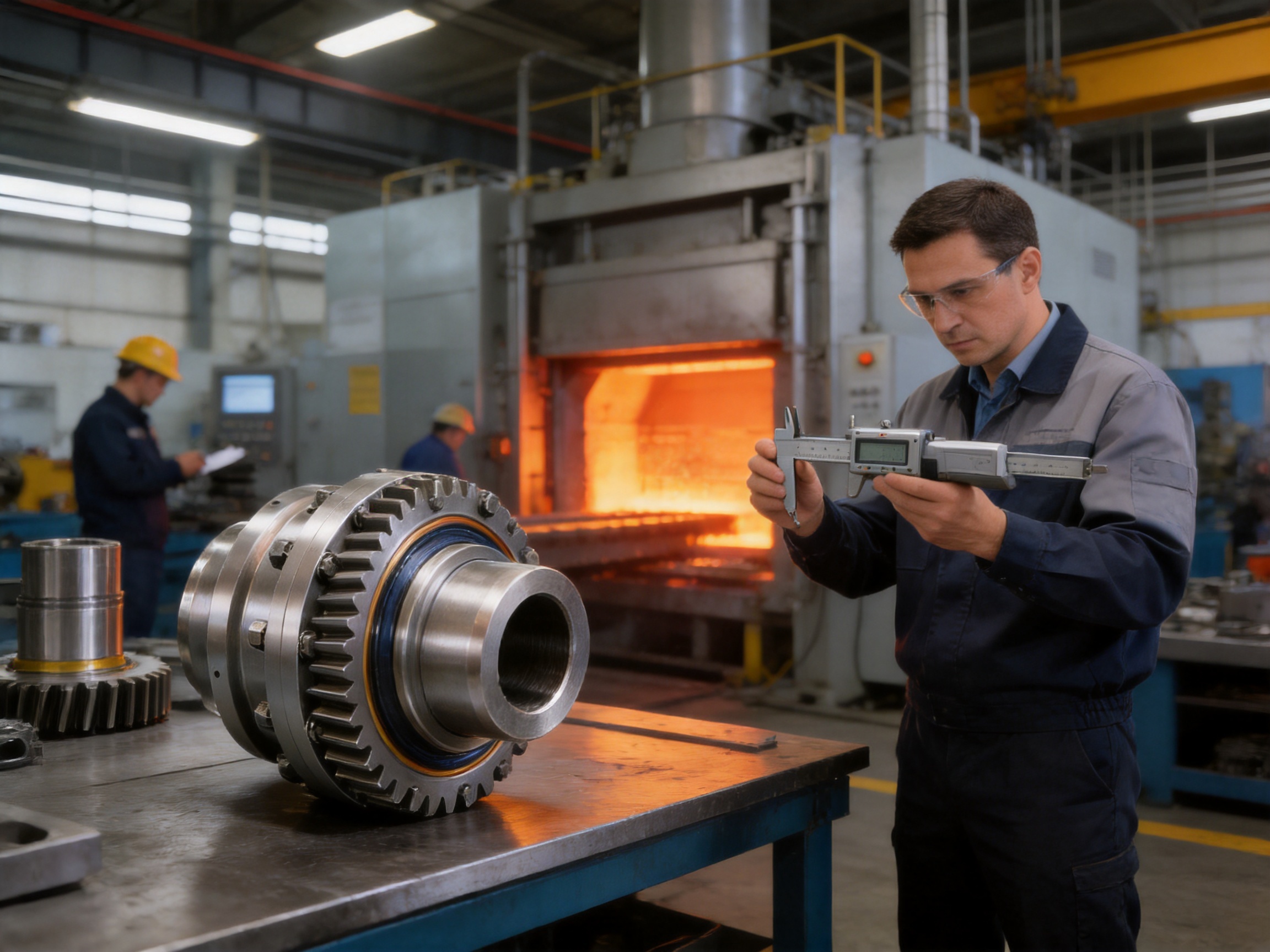
After machining or at the designated stage of production, the gear components undergo carburizing and quenching. Process parameters such as temperature, atmosphere, time, cooling rate, and component positioning must be controlled to achieve consistent case depth and hardness.
Heat treatment may cause dimensional change, so the production process must allow for finishing operations after treatment. Quality checks may include surface hardness, core hardness, case depth, metallographic examination, and distortion measurement.
Finishing and Assembly
After heat treatment, critical surfaces may be ground, honed, or otherwise finished to meet dimensional and surface requirements. The objective is to remove unacceptable distortion, improve tooth contact, and ensure proper fit between mating components.
Assembly includes the inspection and installation of end covers, seals, fasteners, hubs, gear rings, and lubrication-related elements. The assembly process must maintain cleanliness because particles trapped inside the gear chamber can accelerate wear during operation.
Inspection and Testing
Comprehensive inspection helps verify that each coupling meets its engineering requirements. Typical controls may include dimensional inspection, gear tooth inspection, concentricity measurement, runout testing, hardness testing, visual examination, and assembly verification.
Testing procedures should be selected according to the coupling’s size, application, and customer requirements. For specialized or critical equipment, additional checks may be performed to verify balance, material properties, load behavior, or sealing performance.
Quality Management and Manufacturing Strengths
Zhenjiang Orienthold Machinery Co., Ltd. is a medium-sized enterprise specializing in couplings and papermaking machinery. Its operations integrate product design, manufacturing, inspection, and service. This integrated structure enables the company to coordinate technical requirements from the initial inquiry through production, delivery, and after-sales support.
The company operates under a strict quality supervision system and maintains complete inspection and testing equipment. This is important for heavy-duty couplings because product reliability depends on a combination of material quality, tooth accuracy, heat-treatment performance, dimensional control, assembly quality, and correct application selection.
Orienthold Machinery’s products are supplied to customers in transportation, metallurgy, chemical engineering, mining, construction, and hoisting industries. These industries require components that can operate under demanding mechanical and environmental conditions. Experience across these sectors helps the company understand the practical requirements of different drive systems.
The company’s products comply with applicable national standards, while its papermaking machinery technology and quality have reached international levels. Its technical capabilities, production equipment, and inspection resources support the manufacture of couplings for both standard and customized applications.
Another strength is the ability to provide one-stop service. Customers can receive pre-sales technical consultation, product selection support, customization assistance, logistics coordination, payment options, and maintenance support. This reduces the difficulty of coordinating separate design, manufacturing, and service providers.
Customization is particularly valuable for coupling applications. Shaft diameter, bore arrangement, keyway dimensions, flange configuration, installation space, operating speed, environmental protection, and special material requirements may vary from one project to another. A manufacturer with design and production capabilities can adapt the product to the actual equipment rather than forcing the customer to redesign the entire drive system.
Applications in Heavy Industry
Metallurgical Equipment
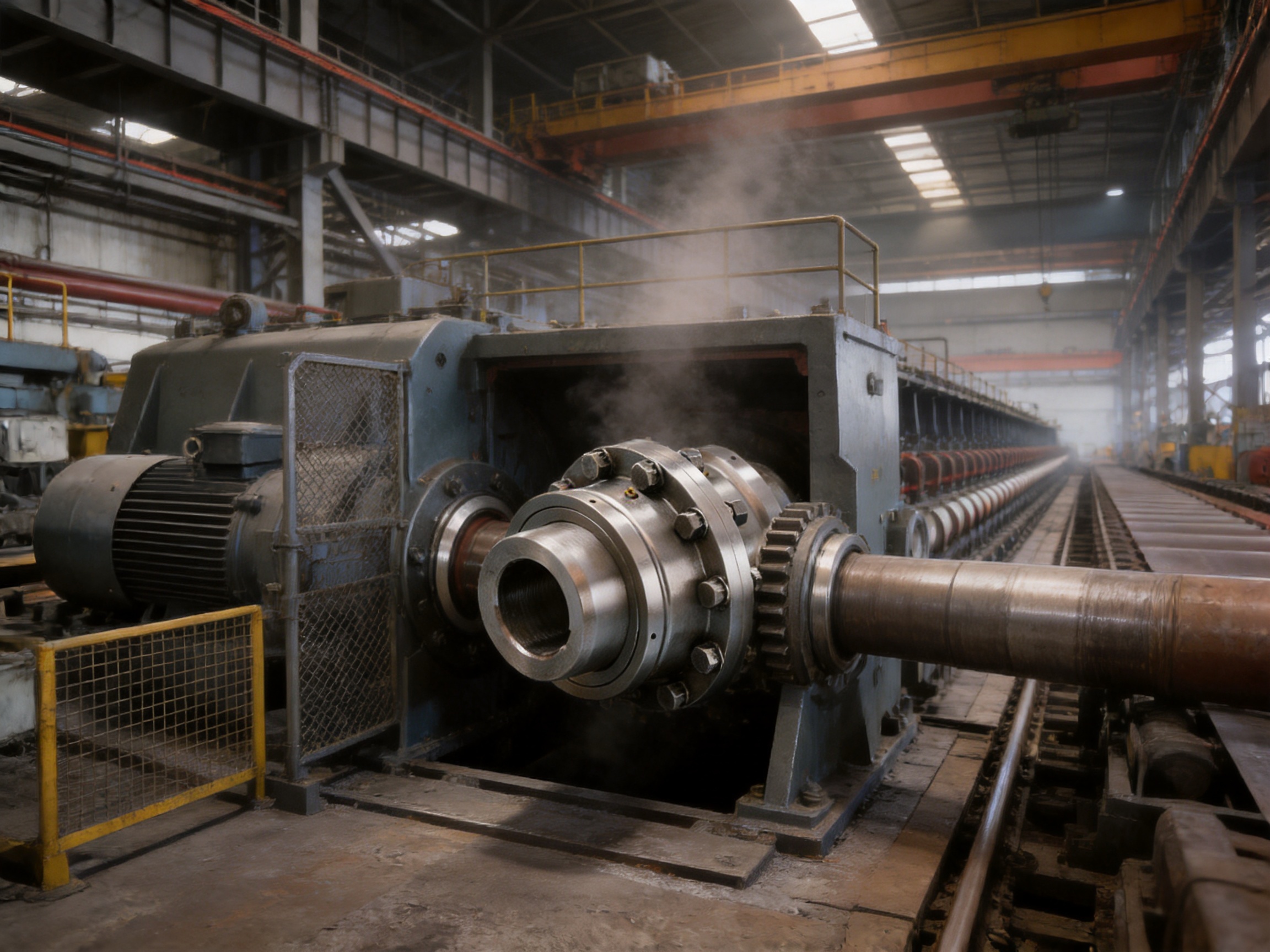
Metallurgical equipment often operates under high torque, elevated temperature, vibration, and impact loading. Rolling mills, continuous casting systems, coil-processing machinery, reheating equipment, and material-handling systems may require couplings with high load capacity and reliable misalignment compensation.
The WG coupling’s large-module gear design and hardened tooth surfaces make it suitable for demanding transmission duties. Its enclosed structure can also help protect the gear engagement from metallic dust and process contamination when properly maintained.
Mining Machinery
Mining conveyors, crushers, screens, bucket elevators, and material-processing systems frequently experience shock loads and fluctuating torque. Conveyors may be exposed to abrasive dust and moisture, while crushers can generate severe transient loads when hard material enters the crushing chamber.
A correctly selected WG coupling can provide the required torque capacity and accommodate limited shaft displacement. The coupling should be selected using the actual starting and peak torque conditions rather than only the motor’s rated power.
Port and Shipyard Machinery
Port cranes, unloaders, winches, conveyors, and transfer systems require dependable power transmission because downtime can interrupt cargo handling operations. Repeated acceleration and braking cycles may place significant demands on the coupling.
The WG coupling can be used in suitable hoisting and conveying drives where its torque capacity, angular compensation, and protective sealing are appropriate. Equipment designers should also evaluate braking torque, emergency stops, wind loads, duty classification, and maintenance accessibility.
Construction and Hoisting Equipment
Construction machinery and hoisting systems often operate intermittently but under severe dynamic conditions. Load pickup, acceleration, deceleration, reversing, and braking can all produce torque fluctuations.
The coupling’s robust gear construction and heat-treated surfaces provide a strong foundation for these applications. Safe operation requires correct service-factor selection, secure fastening, regular inspection, and compliance with the relevant equipment safety requirements.
Papermaking Machinery
Papermaking machinery includes many long-running drives that require stable speed and reliable alignment. Roll drives, process sections, pumps, conveyors, and auxiliary systems may operate continuously for extended periods.
The coupling’s high transmission efficiency and smooth crowned-tooth engagement can help reduce power loss and vibration. The selected design must be matched to the operating speed, shaft arrangement, balance requirements, and environmental conditions of the paper machine.
Chemical and General Industrial Equipment
Chemical plants and general manufacturing facilities use gear couplings in pumps, mixers, fans, compressors, conveyors, and process machinery. Although the torque requirements may vary, these systems often require dependable sealing and resistance to contamination.
When used in chemically aggressive environments, the coupling’s material, coating, lubricant, and sealing compatibility should be reviewed. Additional protection may be required for corrosive atmospheres or washdown conditions.
Installation Recommendations
Correct installation is essential to obtaining the expected performance of any gear coupling. Before installation, the shafts, bores, keyways, mounting faces, and coupling components should be inspected for damage, burrs, corrosion, or contamination.
The shaft centerlines should be aligned as accurately as practical. The coupling’s ability to compensate for misalignment is not a substitute for alignment. Excessive displacement can increase tooth contact stress, lubricant temperature, vibration, and seal wear.
Hub fits and key connections should comply with the engineering requirements of the selected coupling. Improper interference, excessive clearance, damaged keys, or incorrectly positioned shoulders can cause fretting, movement, or stress concentration.
Fasteners should be tightened using the specified sequence and torque. Loose bolts may permit relative movement and fretting, while excessive tightening can damage threads or distort the end-cover structure. Where applicable, locking arrangements should be checked after installation.
The coupling should be filled with the correct lubricant in the correct quantity. Insufficient lubricant can cause rapid tooth wear and overheating. Excessive lubricant may increase churning losses or raise internal pressure. The lubricant must be compatible with the sealing material and the operating temperature.
After installation, the drive should be rotated manually where possible to confirm that there is no binding or abnormal interference. Initial operation should include observation of vibration, noise, temperature, lubricant leakage, and fastening condition.
Maintenance and Service Life
Routine maintenance helps preserve the coupling’s performance and identify problems before they become serious. Inspection intervals should be based on operating hours, duty severity, environmental conditions, manufacturer recommendations, and the consequences of failure.
Maintenance personnel should check for abnormal noise, vibration, overheating, lubricant leakage, loose fasteners, damaged seals, corrosion, and changes in shaft alignment. A sudden increase in vibration may indicate tooth wear, insufficient lubrication, excessive misalignment, bearing problems, or a problem elsewhere in the drive system.
Lubricant condition should be monitored. Contaminated, degraded, or insufficient lubricant can reduce the protective film between the gear teeth. Lubricant replacement should follow the recommended interval and use the specified grade.
Seals should be inspected for hardening, cracking, deformation, or leakage. A damaged seal should be replaced promptly to prevent contamination from entering the gear chamber. Operating a gear coupling without adequate sealing can accelerate tooth wear even when the coupling remains functional in the short term.
Tooth wear should be evaluated during scheduled inspections. Uneven wear patterns may indicate shaft misalignment, excessive load, inadequate lubrication, poor installation, or an unsuitable coupling selection. Corrective action should address the underlying cause rather than simply replacing worn parts.
With appropriate selection, installation, lubrication, and maintenance, the WG coupling can provide a long service life. Its heat-treated gear surfaces, robust construction, and sealing arrangement are designed to support reliable operation in heavy-duty industrial conditions.
Selection Guidelines
Selection should begin with the required transmitted torque. The basic running torque can be calculated from power and speed, but the result must be adjusted for service conditions. Starting, braking, reversing, impact, and load fluctuation may require a higher rated coupling than the normal running torque alone would suggest.
The shaft diameter and available installation space must also be considered. The WG series covers shaft diameters from 12 mm to 400 mm, but the selected bore, hub length, keyway, and mounting arrangement must match the actual shaft design.
Operating speed is another important factor. Higher speed increases the importance of balance, concentricity, tooth accuracy, lubrication, and installation alignment. The coupling’s allowable speed must be confirmed for the specific configuration and operating conditions.
Misalignment should be estimated in all three directions. Angular, radial, and axial displacement may occur together. The selection should not assume that the maximum value for each type of misalignment can be applied simultaneously unless the technical data specifically permits it.
Environmental conditions should be included in the specification. Dust, water, corrosive chemicals, temperature variation, outdoor exposure, washdown, and explosive atmospheres may influence the required sealing, material, lubricant, and protective arrangement.
Other factors include electrical insulation requirements, brake integration, installation orientation, maintenance access, shaft locking method, balancing requirements, and the consequences of unexpected downtime. Customers should provide complete operating information to the manufacturer so that the coupling can be selected or customized appropriately.
Technical Comparison with Alternative Coupling Types
Gear couplings are generally selected when high torque capacity, compact size, and misalignment compensation are required. Their principal advantage is the ability to transmit substantial torque through a gear engagement while allowing shaft movement. Their principal maintenance requirement is proper lubrication and sealing.
Elastic couplings use flexible elements to absorb vibration and accommodate misalignment. They may provide excellent damping and simplified maintenance in moderate-torque applications. However, the flexible element may have limits related to temperature, chemical exposure, fatigue, or torque capacity.
Diaphragm couplings compensate for misalignment through thin metallic diaphragms and are often used in high-speed, precision applications. They can offer low backlash and do not require gear lubrication, but their allowable misalignment and shock-load behavior may differ from those of a heavy-duty gear coupling.
Pin and bush couplings use elastomeric elements to transmit torque and absorb vibration. They can be effective in general industrial drives, but the elastomer may be affected by temperature, oil, chemical exposure, and aging.
Compared with these alternatives, the WG Type Basic Crowned-Gear Coupling is especially appropriate when high torque, heavy shock loading, broad shaft-size coverage, and robust industrial construction are primary requirements. The final choice should always be based on the complete application rather than on one performance characteristic.
Frequently Asked Questions
What is a crowned-gear coupling?
A crowned-gear coupling is a gear coupling in which the external gear teeth have a convex or crowned profile. This geometry allows the tooth contact position to adjust when the connected shafts experience angular or radial misalignment. It helps reduce tooth-edge loading and supports smoother torque transmission.
What is the main advantage of the WG Type Basic Crowned-Gear Coupling?
Its main advantage is the combination of high torque capacity and improved misalignment compensation. The large-module gear design supports heavy-duty loads, while the crowned tooth profile helps maintain more favorable contact when the shafts are not perfectly aligned.
What torque range does the coupling cover?
The stated torque range extends from 710 N·m to 3150 kN·m. The correct model must be selected according to actual running torque, peak torque, speed, service factor, shaft diameter, misalignment, and environmental conditions.
What shaft diameters are available?
The applicable shaft diameter range is from 12 mm to 400 mm. Specific bore dimensions, keyways, hubs, and mounting configurations should be confirmed during technical selection.
How much angular misalignment can the coupling accommodate?
Under zero radial displacement, the permissible angular misalignment can reach up to 1°30′. Actual allowable values depend on the selected model, operating conditions, speed, lubrication, and whether other types of misalignment occur simultaneously.
Does the coupling eliminate the need for shaft alignment?
No. The coupling compensates for limited operational and installation misalignment, but accurate alignment remains necessary. Excessive misalignment can increase tooth stress, vibration, seal wear, and lubricant temperature.
Why are carburizing and quenching used?
Carburizing and quenching create a hard, wear-resistant surface on the gear teeth while retaining a tougher internal core. This combination helps the coupling resist contact wear, fatigue, impact, and tooth damage during heavy-duty operation.
Is lubrication required?
Yes. The gear teeth require suitable lubrication to reduce friction, wear, and heat generation. The correct lubricant type, quantity, inspection interval, and replacement schedule should be determined from the applicable technical documentation and operating conditions.
Can the coupling be customized?
Customization may be available for bore dimensions, keyways, mounting arrangements, materials, sealing details, and other application-specific requirements. Customers should provide shaft data, torque, speed, misalignment, environment, and installation information for evaluation.
Which industries commonly use this type of coupling?
Typical industries include metallurgy, mining, transportation, port machinery, construction, hoisting, papermaking, chemical engineering, and general heavy equipment manufacturing.
What inspection points are most important during maintenance?
Important inspection points include lubricant condition and quantity, seal condition, abnormal noise, vibration, temperature, fastener security, tooth wear, corrosion, shaft alignment, and signs of overload or impact damage.
How does Orienthold Machinery support customers?
Zhenjiang Orienthold Machinery Co., Ltd. provides design, production, inspection, technical consultation, customization, logistics coordination, and maintenance support. Its integrated service structure is intended to help customers obtain a suitable coupling solution from selection through operation.
Why Choose a Specialized Coupling Manufacturer?
A coupling is a precision transmission component, and its performance depends on more than its external dimensions. Tooth geometry, heat treatment, material quality, sealing, machining accuracy, assembly, and inspection all influence reliability. Working with a specialized manufacturer helps ensure that these factors are considered together.
A specialized producer can also evaluate the relationship between the coupling and the connected equipment. For example, a coupling used in a rolling mill may require different design considerations from one used in a conveyor, hoist, pump, or paper machine. Application knowledge helps reduce the risk of selecting a product based solely on nominal torque.
Orienthold Machinery combines coupling production with engineering and service capabilities. Its experience in transportation, metallurgy, chemical engineering, mining, construction, and hoisting gives it exposure to a broad range of industrial operating conditions.
The company’s manufacturing resources, quality supervision system, inspection equipment, and customization capability support projects that require both standard products and application-specific solutions. This is particularly useful for replacement projects where the original coupling is no longer available or where the equipment has been modified.
Conclusion
The WG Type Basic Crowned-Gear Coupling is engineered for industrial drive systems that demand high torque capacity, dependable misalignment compensation, efficient power transmission, and resistance to harsh operating conditions. Its large-module gear structure provides the strength required for heavy-duty service, while the crowned external tooth profile helps distribute load more evenly when shaft displacement occurs.
The coupling’s torque range of 710 N·m to 3150 kN·m and shaft diameter coverage of 12 mm to 400 mm provide broad application flexibility. Its stated transmission efficiency of up to 99.7% supports economical operation, while the permissible angular misalignment of up to 1°30′ under zero radial displacement improves tolerance to practical installation and operating deviations.
High-strength alloy steel, carburizing, quenching, precision machining, controlled gear production, sealing, and inspection work together to create a durable transmission component. These manufacturing processes are supported by Orienthold Machinery’s integrated design, production, quality control, customization, and customer-service capabilities.
For metallurgy, mining, port machinery, construction, hoisting, papermaking, and other heavy industrial applications, the WG coupling offers a balanced combination of torque strength, flexibility, efficiency, and environmental protection. Correct selection, alignment, lubrication, and maintenance remain essential, but the product’s design provides a strong foundation for reliable long-term operation.
References
1. General principles of industrial shaft coupling selection, torque calculation, service factors, and misalignment evaluation.
2. Gear transmission engineering practices for tooth contact, surface durability, bending strength, lubrication, and fatigue resistance.
3. Heat-treatment principles for carburized and quenched alloy-steel mechanical components.
4. Industrial machinery maintenance practices for gear couplings, including alignment, lubrication, sealing inspection, and vibration monitoring.
5. Manufacturer-provided technical information for the WG Type Basic Crowned-Gear Coupling.
6. Manufacturer-provided information concerning industrial coupling production, quality supervision, customization, inspection, and customer service.
Product: WG Type Basic Crowned-Gear Coupling
PREV: LX(HL) Elastic Pin Coupling: Reliable Torque Transmission for Industrial MachineryNEXT: WGP Type Crowned-Gear Coupling with Brake Disc: Integrated Torque Transmission and Reliable Braking for Heavy-Duty Machinery
Be the First to Know
For exclusive deals and latest offers, sign up by entering your email address below.
Related products
News
-
-
Two quotes land for the same replacement gear coupling: $1,850 from one shop and $2,600 from another. Both promise stan...
READ MORE -
A mill drive rarely fails without warning. It knocks at speed, throws a smear of dark grease around the sleeve flange, ...
READ MORE -
Gear Coupling vs. Drum Gear Coupling: The Core Difference The main difference is that "gear coupling" is a broad catego...
READ MORE -
China's coupling industry is at a critical historical juncture of transformation from scale expansion to quality and eff...
READ MORE -
Industrial Couplings: The Definitive Technical Encyclopedia – Classification, Sizing, Failure Prevention, and Lifecycle...
READ MORE


ABOUT US
PRODUCTS
INDUSTRIES
CONTACT US
- Phone: +86-18652865511
- Email: sales@ohmach.com
- Address: No.1, Minying Developing Zone, Zhenjiang, Jiangsu, China
Copyright Zhenjiang Orienthold Machinery Co., Ltd. All Rights Reserved.
 Custom Industrial Shaft Coupling Manufacturers