 English
 русский
 Português
 عربى
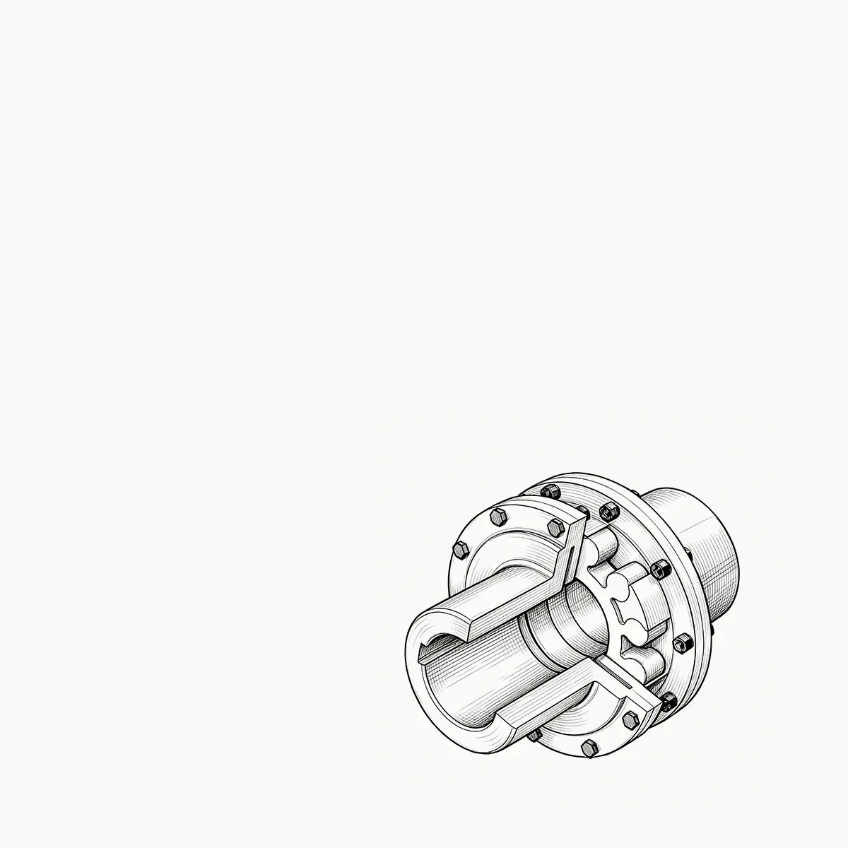
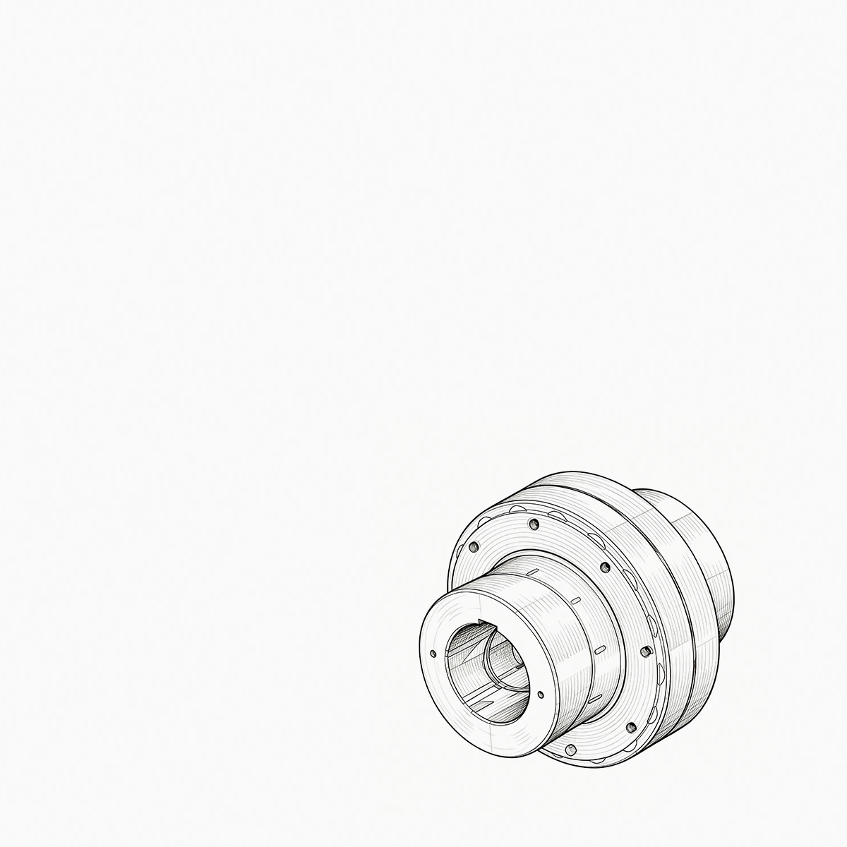
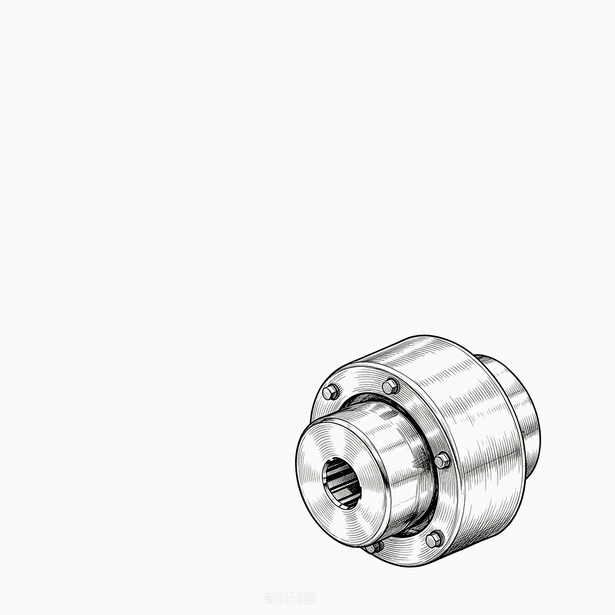
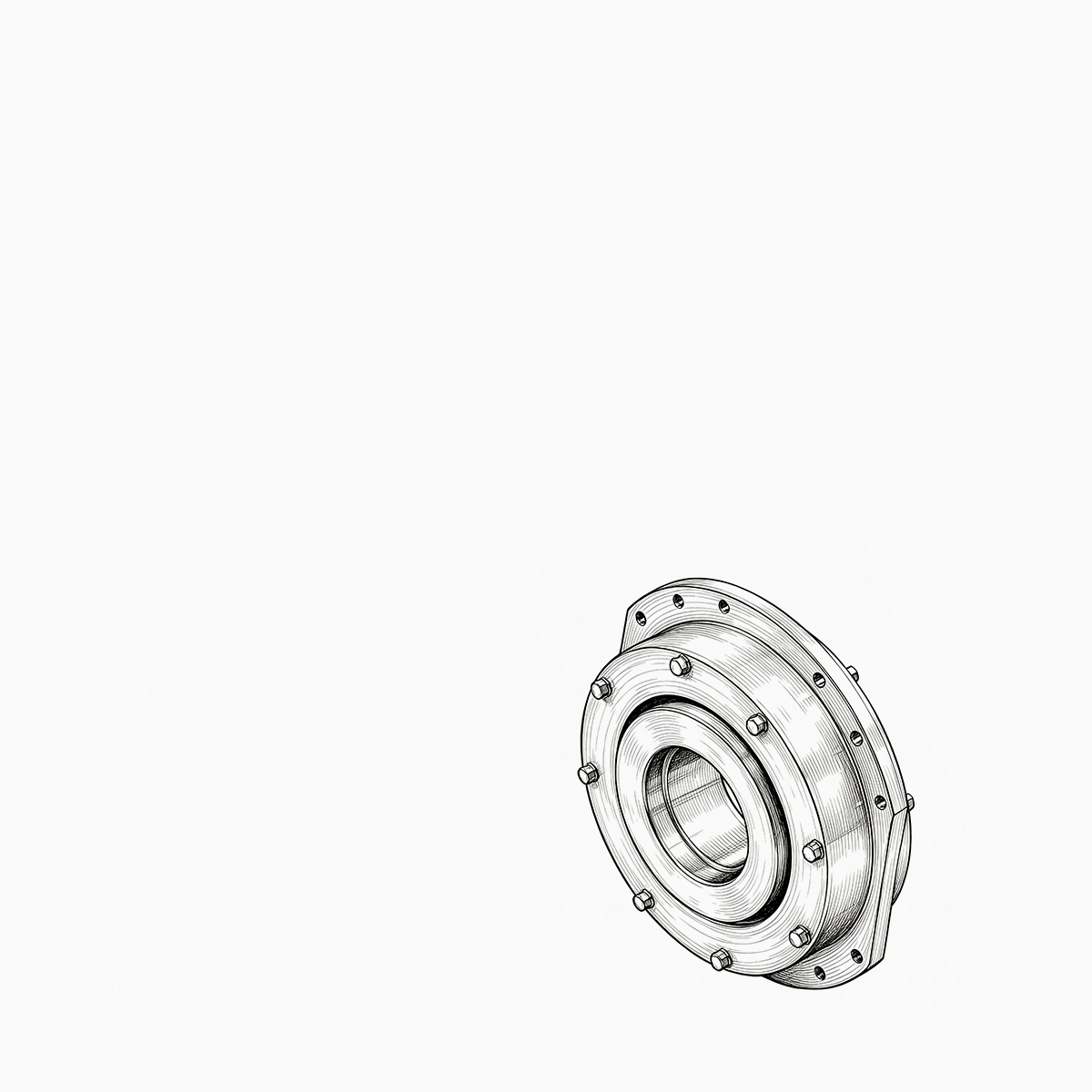

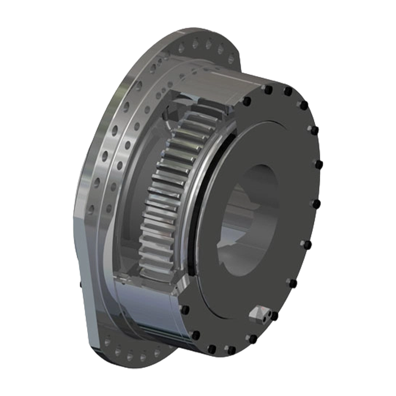
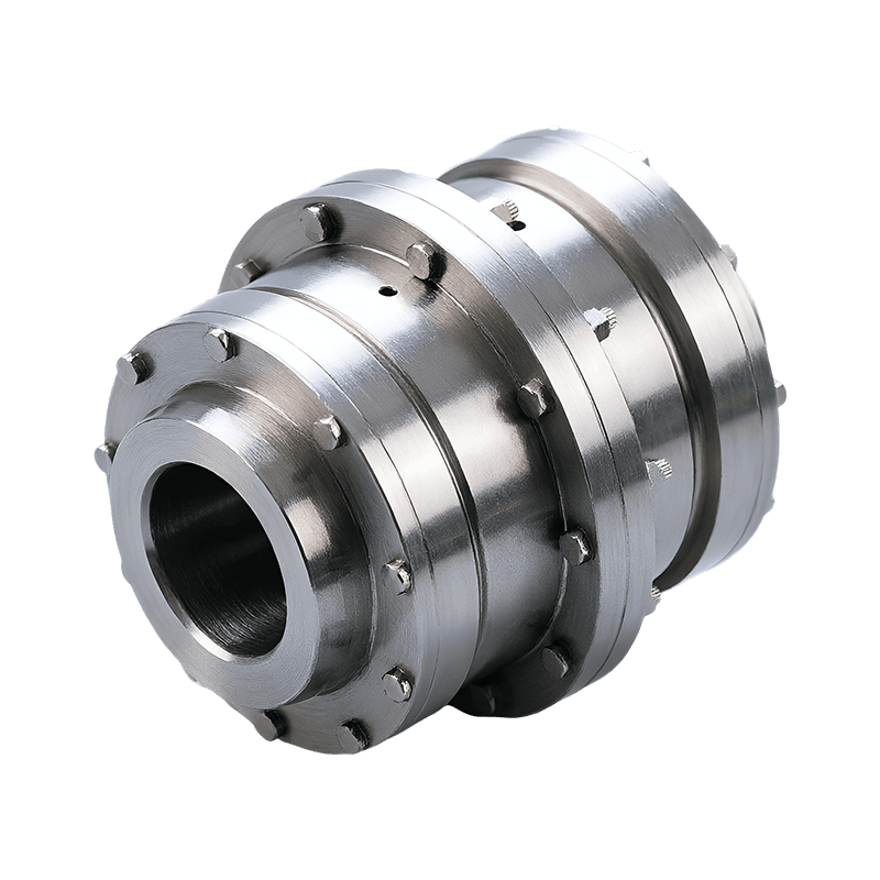
Consider a 250 kW crane hoist that begins to vibrate only when the load is lifted. The drum gear coupling is inspected ...
READ MORE
WGP Type Crowned-Gear Coupling with Brake Disc: Integrated Torque Transmission and Reliable Braking for Heavy-Duty Machinery
Admin 2026-09-05Content
- 1 Product Overview and Operating Purpose
- 2 Structural Configuration
- 3 How Crowned Gear Tooth Geometry Improves Flexibility
- 4 Brake Torque Transmission and Mechanical Safety
- 5 Performance Advantages Compared with Alternative Coupling Arrangements
- 6 Manufacturing Quality and Engineering Capabilities
- 7 Application Areas
- 8 Installation Recommendations
- 9 Lubrication and Maintenance
- 10 Selection Considerations
- 11 Customization and Technical Service
- 12 Why Manufacturing Strength Matters to Coupling Buyers
- 13 Reliability, Efficiency, and Total Operating Value
- 14 Q&A
- 14.1 What is the main function of the WGP crowned-gear coupling with brake disc?
- 14.2 How does the crowned tooth design differ from a standard straight gear tooth?
- 14.3 Does the coupling eliminate the need for shaft alignment?
- 14.4 How is the brake disc connected to the coupling?
- 14.5 Can the coupling be used with any disc brake?
- 14.6 What industries commonly use this type of coupling?
- 14.7 What information is required for product selection?
- 14.8 What maintenance does the coupling require?
- 14.9 Can the coupling be customized?
- 14.10 Why is the brake torque path important?
- 14.11 Is the WGP coupling suitable for emergency braking?
- 14.12 What makes the product competitive in heavy-duty applications?
- 15 Conclusion
- 16 References
- 17 Product: WGP Type Crowned-Gear Coupling with Brake Disc
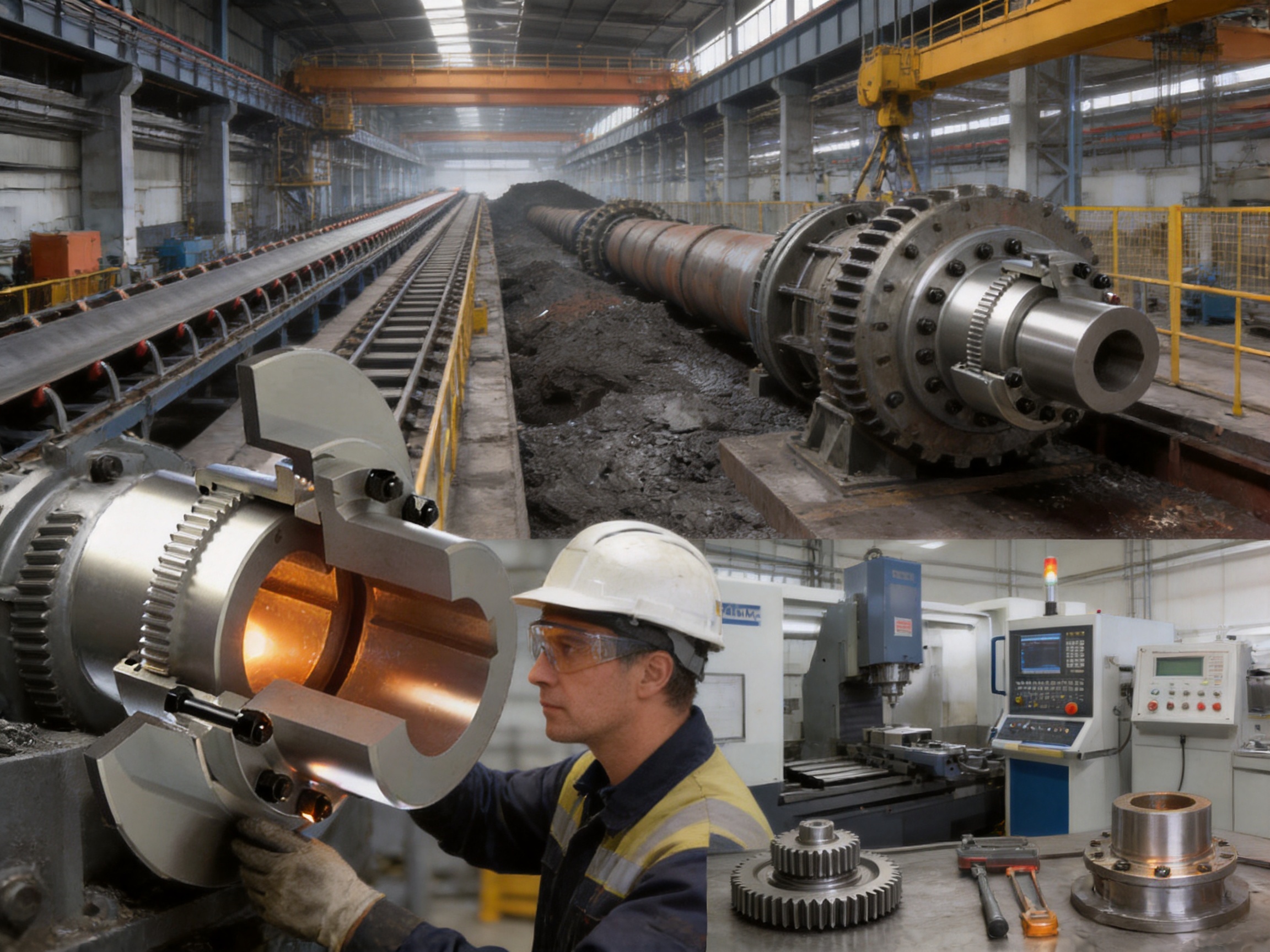
Modern industrial drive systems must perform two essential functions at the same time: transmit torque efficiently and stop or control rotating equipment safely. In many applications, these functions are handled by separate components. A shaft coupling transfers power between connected shafts, while a disc brake provides controlled deceleration or holding torque. The WGP type crowned-gear coupling with brake disc combines these functions into one coordinated mechanical assembly, creating a compact and dependable solution for demanding transmission systems.
This coupling belongs to the drum gear coupling family and is designed specifically for applications in which a disc brake must operate together with a flexible shaft connection. It is particularly suitable for metallurgy, lifting and conveying equipment, mining machinery, construction machinery, transportation systems, and other heavy-duty installations. Its main engineering value comes from the combination of crowned external gear teeth, a matching internal-toothed sleeve, a rigidly mounted brake disc, and a compact symmetrical arrangement.
Unlike a conventional rigid shaft connection, the WGP coupling can accommodate angular, axial, and radial misalignment. Unlike a basic gear coupling without integrated braking provisions, it provides a defined mechanical interface for a disc brake system. Unlike many separately assembled coupling-and-brake arrangements, it offers a coordinated load path that can reduce installation complexity and help protect the gear-meshing area from direct braking shock.
Product Overview and Operating Purpose
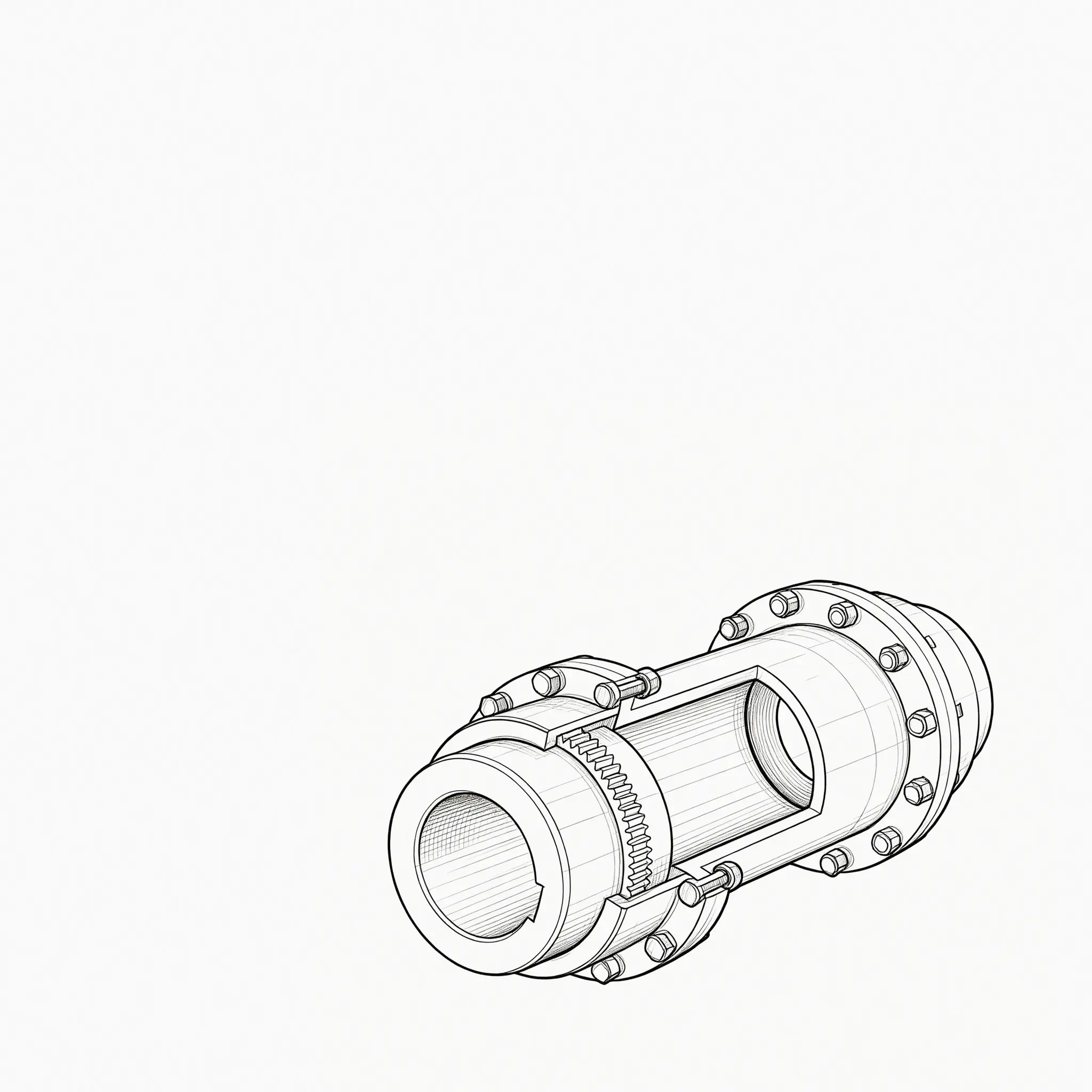
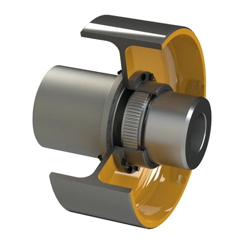
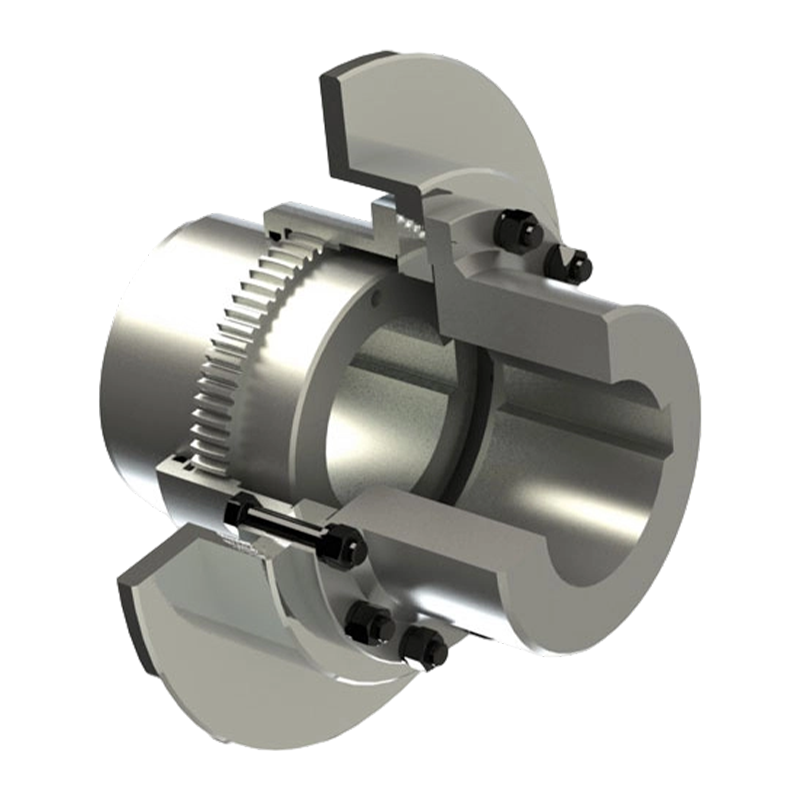
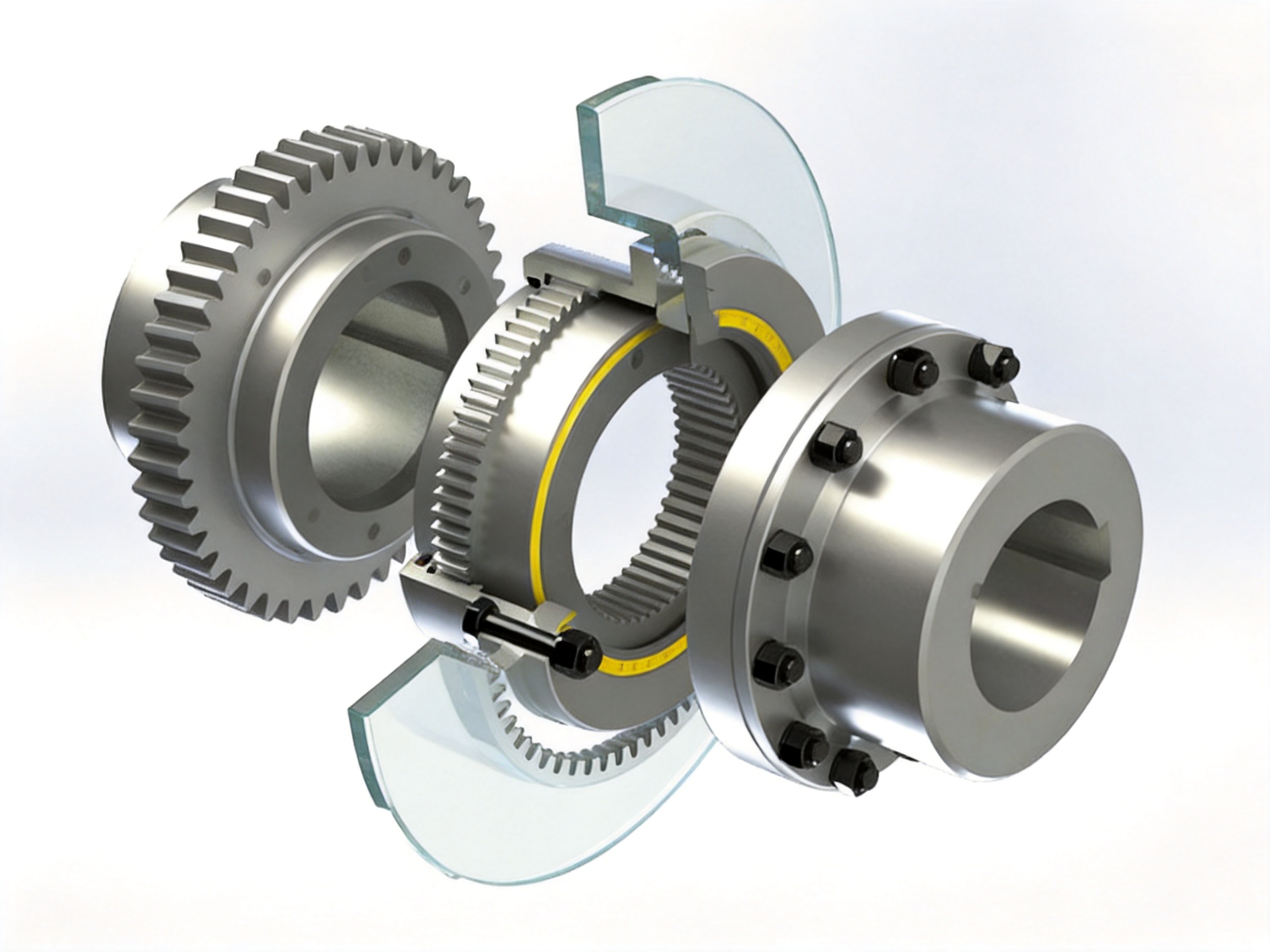
The WGP type crowned-gear coupling with brake disc is a flexible power transmission component intended to connect two shafts while allowing controlled relative movement between them. Its left and right hubs are connected through a sleeve and flange arrangement. One hub carries crowned external teeth, which engage with internal teeth formed inside the sleeve. The opposite hub is joined to the sleeve through a flange secured with high-strength bolts. The brake disc is clamped firmly between the flange and the sleeve.
This configuration allows the coupling to transmit rotational torque while also providing a mounting and reaction structure for the brake disc. During normal operation, torque flows through the hubs, crowned gear teeth, sleeve, flange, and connected shafts. During braking, the disc brake acts on the integrated brake disc, and the resulting braking torque is transferred through the flange and right hub. Because the brake disc is structurally associated with the sleeve and flange, braking forces can be directed through a controlled path rather than being concentrated unnecessarily at the flexible tooth engagement area.
The coupling is therefore more than a simple shaft connector. It is an integrated mechanical interface between a rotating drive train and a braking system. The design is intended to maintain reliable power transmission during acceleration and steady operation, while also supporting predictable braking response during deceleration, emergency stopping, positioning, or load holding.
Applications may include hoisting mechanisms, traveling drives, winches, conveyors, rolling mills, crushers, lifting platforms, mining equipment, and other machinery in which high torque, frequent starting and stopping, or substantial rotating inertia are present. The actual selection must always be based on the required torque, speed, bore dimensions, braking torque, duty cycle, environmental conditions, and applicable design standards.
Structural Configuration
Left Hub with Crowned External Teeth
The left hub is machined with crowned external teeth at its end. These teeth are the primary flexible transmission interface within the coupling. They engage with the internal teeth of the sleeve and transmit torque through a broad series of mating tooth surfaces.
The crowned profile is not simply a decorative modification to a standard gear tooth. It is a deliberate geometric design that allows the tooth contact pattern to adapt when the connected shafts are not perfectly collinear. The tooth surface is formed with a spherical or barrel-shaped profile, with the center of curvature associated with the gear axis. This geometry allows the sleeve and hub to articulate relative to one another while retaining effective tooth contact.
When shaft alignment changes under load, the crowned teeth help prevent the outer edges of the tooth flanks from carrying an excessive share of the load. Instead, the contact area can shift progressively along the tooth width. This reduces the risk of severe edge loading and contributes to smoother torque transfer.
Right Hub and Connecting Flange
The right hub is connected to the sleeve through a flange. High-strength bolts secure the flange and help maintain the structural integrity of the assembly under torque and braking loads. The flange is also an important part of the brake-disc mounting arrangement.
By using a bolted flange connection, the assembly can be manufactured, inspected, installed, and serviced in a practical manner. The bolted design provides a firm mechanical joint while allowing controlled disassembly when inspection or replacement is necessary. Correct bolt grade, tightening sequence, tightening torque, and joint surface condition are essential to achieving the intended performance.
Internal-Toothed Sleeve
The sleeve surrounds and engages with the crowned external teeth of the hub. It provides the internal tooth geometry required for torque transmission and forms part of the outer structural envelope of the coupling. The sleeve must be manufactured with accurate tooth spacing, appropriate backlash, and suitable concentricity relative to the flange and brake-disc mounting surfaces.
The sleeve also helps distribute forces around the coupling circumference. Its compact form contributes to reduced installation space compared with systems that use an independent shaft coupling and a separately mounted brake rotor. Depending on the application, the sleeve may also be designed with inspection, lubrication, sealing, or maintenance provisions appropriate to the operating environment.
Integrated Brake Disc
The brake disc is positioned between the flange and sleeve and is firmly clamped into the assembly. This arrangement creates a direct mechanical relationship between the brake disc and the right hub. A compatible disc brake caliper or braking mechanism can apply friction to the disc to generate deceleration or holding torque.
The brake disc must be sufficiently rigid and dimensionally stable to withstand repeated thermal and mechanical loading. Its friction surfaces should remain flat, clean, and free from distortion. The braking system must be selected so that its braking torque, heat dissipation capability, response time, and duty cycle are compatible with the coupling and the driven machine.
Symmetrical and Compact Arrangement
The WGP design uses a symmetrical and compact configuration. This helps reduce unnecessary overhang and can simplify the integration of the coupling into an existing drive system. A compact arrangement may also reduce the amount of supporting structure required around the shaft line, although the final installation must provide adequate clearance for the brake caliper, inspection, lubrication, and maintenance.
Symmetry can contribute to balanced operation when the rotating components are manufactured and assembled correctly. It may also help distribute mechanical loads more evenly around the coupling. Dynamic balancing requirements depend on the operating speed, rotor mass, shaft arrangement, and applicable equipment standards.
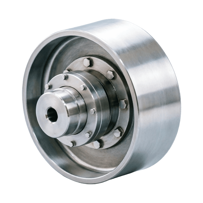
WGP Type Crowned-Gear Coupling with Brake Disc
How Crowned Gear Tooth Geometry Improves Flexibility
The central performance feature of the WGP coupling is its crowned gear tooth design. A conventional straight-sided gear engagement is highly sensitive to shaft misalignment. When two connected shafts are not perfectly aligned, the tooth flanks may contact primarily at one edge. This can create high local stress, uneven wear, vibration, and accelerated deterioration.
In a crowned gear coupling, the external teeth are curved across their width. The tooth thickness gradually changes toward both sides, and increased backlash is provided between the mating teeth. Together, these features allow the hub and sleeve to articulate while maintaining useful engagement.
Angular Misalignment Compensation
Angular misalignment occurs when the centerlines of two connected shafts intersect at an angle rather than forming one straight line. This may result from installation tolerances, foundation movement, frame deformation, bearing displacement, or thermal expansion.
The crowned tooth surface allows the sleeve to tilt relative to the hub without forcing the tooth edges into severe interference. As the angle changes, the contact zone moves over the curved tooth surface. This helps maintain a more favorable load distribution than a straight-tooth arrangement would provide.
Angular flexibility is especially valuable in long or heavy machine trains. Even when shafts are carefully aligned during commissioning, operating loads can change the position of gearboxes, drums, motors, or driven machinery. A flexible coupling can absorb a portion of these changes and reduce the transmission of unwanted bending forces to connected bearings.
Axial Movement Accommodation
Axial displacement occurs when shafts move along their common axis. Thermal growth is a frequent cause, particularly in equipment with long shafts, large temperature differences, or high operating temperatures. Axial movement may also be associated with bearing clearances, structural deflection, or assembly tolerances.
The clearance and tooth geometry of the crowned gear engagement allow limited axial movement while retaining torque-transmitting contact. The exact allowable displacement depends on the coupling size, tooth design, lubrication, speed, load, and manufacturer specifications. The coupling should not be used as a substitute for a dedicated thrust-control system, but its flexibility can prevent minor axial movement from becoming a harmful constraint.
Radial Misalignment Compensation
Radial misalignment occurs when two shafts are parallel but offset from one another. It may be caused by foundation settlement, bearing movement, thermal changes, or inaccuracies in mounting. In a crowned gear coupling, the articulated relationship between the hub and sleeve can accommodate a degree of radial offset.
Radial flexibility reduces the tendency for the connected shafts to impose excessive reaction loads on one another. This is important for bearing life and for the stability of the overall drive system. However, excessive radial displacement can still produce high tooth pressure, heat, and wear. Alignment should therefore be corrected during installation rather than relying entirely on coupling flexibility.
Double-Articulated Transmission Behavior
The coupling can function as a double-articulated flexible transmission element. This means that the gear engagement and structural arrangement permit controlled movement in more than one direction while the coupling continues to transmit torque. The result is a more tolerant shaft connection than a rigid flange coupling or a basic sleeve connection.
This flexibility is one of the principal advantages of the WGP design over less adaptable coupling types. It does not eliminate the need for alignment, but it increases the operating tolerance of the machine and can reduce the consequences of unavoidable displacement.
Brake Torque Transmission and Mechanical Safety
In a drive system with a separate coupling and brake disc, the relationship between the brake and coupling must be carefully engineered. The brake may be mounted on an adjacent shaft, gearbox input, gearbox output, or an independent brake shaft. Each arrangement creates a different torque path and may expose the coupling or gear teeth to braking shocks.
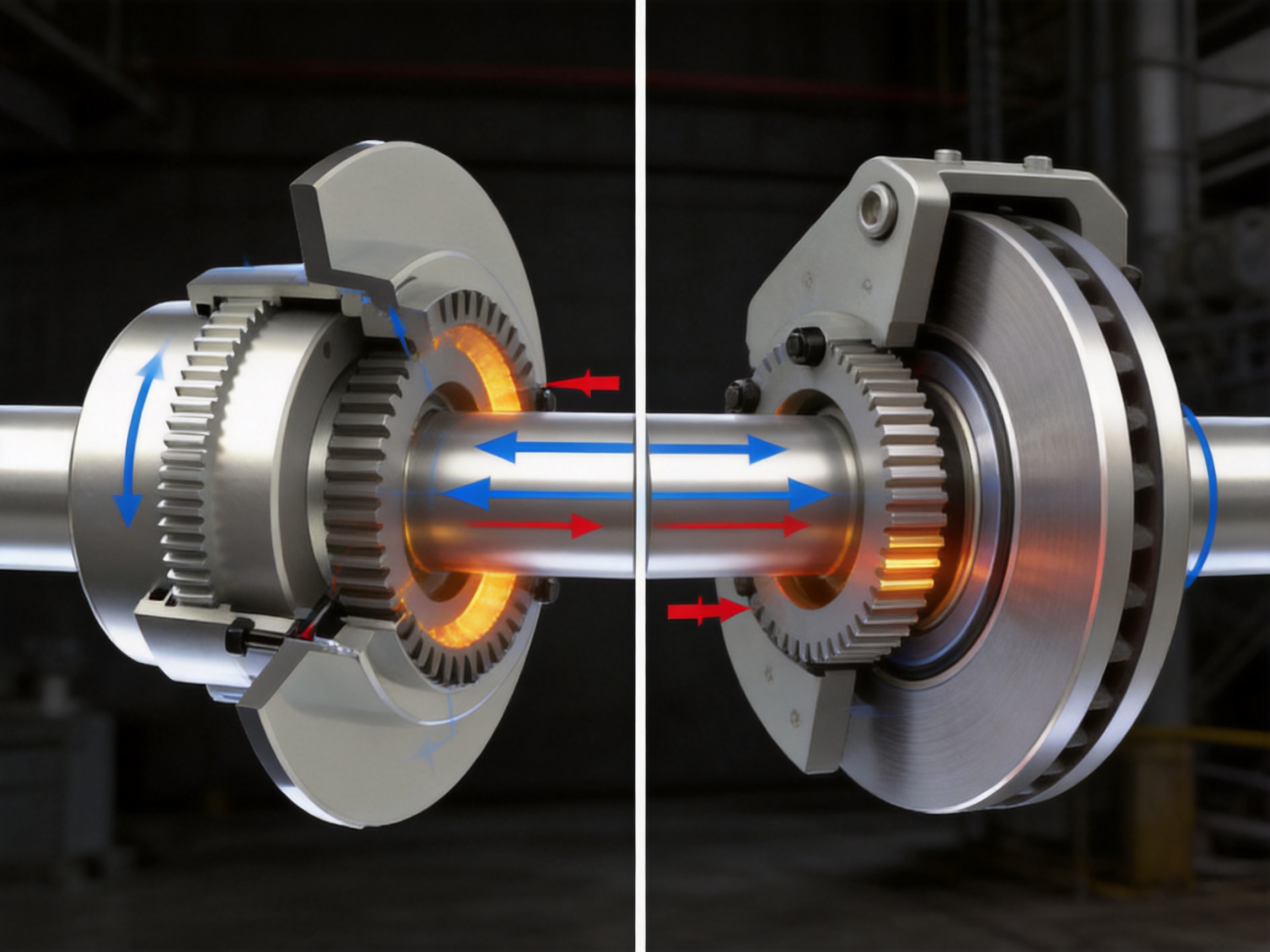
The WGP coupling places the brake disc within the coupling structure. The disc is clamped between the flange and sleeve, and the braking torque is transmitted through the right hub. This arrangement can reduce the direct impact of braking forces on the gear meshing area. The gear teeth remain responsible primarily for flexible torque transmission, while the flange and right hub provide a defined route for braking torque.
This separation of functional load paths can improve operating stability. When the brake is applied, the braking torque is carried through the components intended to support it. The result can be more consistent tooth contact and less disturbance to the flexible engagement compared with an arrangement in which the brake reaction is introduced unpredictably through the coupling teeth.
Brake torque must be evaluated in relation to the transmitted motor torque, driven load torque, reflected inertia, stopping time, rotational speed, and braking frequency. The peak torque during an emergency stop may be considerably higher than the steady operating torque. The coupling, flange, bolts, hub, shaft keys, and brake disc must all be checked for the most severe applicable load case.
Braking energy is another important consideration. The kinetic energy of the rotating system is converted primarily into heat at the brake friction interface. If braking is frequent, the brake disc and caliper must dissipate heat without excessive temperature rise, distortion, or reduction in friction performance. A coupling that mechanically supports the brake disc does not replace the need for correct thermal sizing of the braking system.
Performance Advantages Compared with Alternative Coupling Arrangements
Compared with Rigid Flange Couplings
Rigid flange couplings provide a strong and direct connection, but they offer little or no compensation for angular, axial, or radial misalignment. Any displacement between the shafts is transferred to the bearings, shafts, and connected equipment. In a heavy-duty machine, this can increase bearing loads and contribute to vibration or premature wear.
The WGP coupling provides a more forgiving connection through its crowned gear teeth. It can accommodate operating displacement while maintaining torque transmission. This flexibility is a significant advantage where thermal expansion, structural movement, or installation tolerances cannot be completely eliminated.
Compared with Straight-Tooth Gear Couplings
A straight-tooth gear coupling may transmit high torque, but its ability to tolerate misalignment is more limited when compared with a properly designed crowned gear coupling. Straight tooth flanks can develop concentrated edge contact under angular displacement. The crowned geometry of the WGP coupling helps distribute contact more progressively and reduces the risk of localized stress.
The crowned profile also promotes smoother articulation. This can help reduce vibration and tooth impact, particularly when the machine experiences repeated load changes, starting cycles, or braking events.
Compared with Elastomeric Couplings
Elastomeric couplings are valued for their damping properties, simplicity, and ability to absorb torsional vibration. However, elastomer performance can be influenced by temperature, chemical exposure, aging, ultraviolet radiation, and fatigue. In very high-torque or high-load applications, an elastomeric element may require substantial dimensions or may have a more limited service life.
The WGP coupling uses metallic gear components and is intended for heavy-duty torque transmission. It is therefore well suited to applications in which high mechanical strength, compact dimensions, and robust load capacity are more important than the high torsional damping of an elastomeric element. The two coupling types serve different design priorities, and selection should be based on the actual operating conditions.
Compared with Separate Coupling and Brake Assemblies
A separate coupling and brake arrangement can provide design flexibility, but it may require more space, additional shafting, extra supports, and more alignment work. It can also create multiple interfaces where backlash, fastener loosening, or installation errors may occur.
The integrated WGP configuration combines shaft flexibility and brake-disc mounting within a coordinated assembly. This can simplify the mechanical layout and reduce the number of major components in the drive train. It also provides a clearly defined relationship between the brake disc, flange, sleeve, and hub.
Compared with Basic Drum Couplings without Braking Integration
A standard drum gear coupling can provide flexible torque transmission but may require a separate brake rotor or brake drum. The WGP type is advantageous when the machine requires a disc brake and the available installation space favors an integrated arrangement.
Its brake-disc mounting structure can support more orderly force transfer and reduce the need to adapt a standard coupling with improvised brackets or auxiliary hubs. This may improve installation quality and make the overall drive system easier to engineer.
| Design consideration | WGP crowned-gear coupling with brake disc | Rigid flange coupling | Elastomeric coupling | Separate coupling and brake arrangement |
|---|---|---|---|---|
| Angular misalignment compensation | Strong capability through crowned gear articulation | Very limited | Generally available, depending on element design | Depends on the selected coupling |
| Axial movement accommodation | Available within specified limits | Usually limited | Depends on the element and assembly | Depends on the coupling and brake layout |
| High-torque suitability | Well suited to heavy-duty metallic transmission | High, but alignment-sensitive | Application-dependent | Depends on individual components |
| Disc brake integration | Purpose-designed brake disc mounting | Normally requires additional components | Normally requires additional components | Requires separate mounting and interfaces |
| Resistance to high mechanical loads | High when correctly selected and maintained | High under accurate alignment | Limited by elastomer properties and fatigue | Dependent on system integration |
| Space efficiency | Compact combined arrangement | Compact coupling but separate brake space may be needed | Usually compact, but brake integration varies | Potentially greater installation envelope |
| Maintenance priority | Gear lubrication, brake inspection, fastener checks | Alignment and fastener checks | Element inspection and replacement | Separate maintenance of coupling and brake |
Manufacturing Quality and Engineering Capabilities
The performance of a crowned-gear coupling depends heavily on manufacturing accuracy. The design concept is effective only when the tooth geometry, hub concentricity, flange position, bolt holes, brake-disc surfaces, and overall balance are produced within appropriate tolerances.
The manufacturer behind this product specializes in industrial couplings and papermaking machinery, integrating product design, production, and technical service. This combination is valuable because coupling performance is influenced not only by machining but also by application engineering. A manufacturer that understands complete machine systems can better evaluate shaft arrangements, installation constraints, load patterns, and maintenance requirements.
Engineering and Product Design
Product development begins with understanding the intended duty. Engineers must consider rated torque, peak torque, rotational speed, shaft diameters, bore tolerances, misalignment, braking torque, environmental conditions, lubrication, and installation space. For lifting and conveying equipment, starting and stopping cycles may be more important than steady-state torque. For metallurgical machinery, temperature and contamination may dominate the design requirements.
Computer-aided design and engineering analysis can be used to refine the hub, sleeve, flange, and brake-disc arrangement. Design reviews may focus on tooth contact, bolt loading, stress concentration, shaft connection, disc stiffness, thermal clearance, and service access. Proper design coordination helps ensure that the coupling functions as part of the complete transmission rather than as an isolated component.
Precision Machining
The crowned tooth profile requires controlled machining. Tooth form, pitch, flank accuracy, surface finish, and concentricity all influence load distribution and operating smoothness. Inaccurate tooth geometry can create uneven contact, backlash variation, noise, and accelerated wear.
Precision turning and gear-machining processes are used to produce the hubs and sleeve. Machining centers and controlled inspection procedures can help maintain dimensional consistency across production batches. Critical surfaces such as hub bores, flange faces, locating diameters, and brake-disc mounting surfaces require particular attention because they influence alignment and runout.
The machining process should also provide appropriate transitions at shoulders, keyways, and fillets. Sudden changes in cross-section can produce stress concentrations, especially when the coupling experiences alternating torque or braking shocks. Careful geometry and surface quality improve fatigue resistance.
Material and Heat-Treatment Control
Coupling hubs, sleeves, flanges, and bolts must be manufactured from materials suitable for the expected torque, speed, shock loading, and environment. Material selection is normally based on strength, toughness, hardenability, wear resistance, machinability, and compatibility with heat treatment.
Gear tooth surfaces may require a controlled hardness profile to provide wear resistance while retaining sufficient toughness beneath the surface. Heat treatment must be carefully managed to limit distortion. After treatment, critical dimensions and tooth geometry should be rechecked. Where necessary, finishing operations can restore the required fit and contact accuracy.
The brake disc material and surface condition must be compatible with the selected friction lining and operating temperature. Disc flatness, runout, and thickness uniformity are important for smooth braking and reduced caliper vibration.
Inspection and Testing
A comprehensive inspection system may include verification of raw materials, dimensional inspection during machining, tooth-profile checks, runout measurement, surface inspection, hardness testing, bolt and flange checks, and final assembly verification.
Inspection of the crowned teeth is particularly important. The mating components should be checked for correct engagement, backlash, contact pattern, and freedom of articulation. The brake disc should be checked for axial runout and mounting integrity. The complete assembly may also be examined for balance and rotational interference.
Testing methods should be selected according to the component size, application risk, and customer requirements. Non-destructive examination may be appropriate for critical parts or high-load applications. Functional testing can verify assembly fit, rotation, brake-disc clearance, and basic mechanical operation before shipment.
Quality Supervision System
The manufacturer operates under a strict quality supervision system supported by inspection and testing equipment. A structured quality system helps control production from material receipt through machining, assembly, final inspection, packaging, and delivery.
Traceability is also valuable. Maintaining records for materials, heat treatment, inspection results, and assembly checks can support consistent production and simplify technical communication. For customers operating large fleets of industrial equipment, repeatable quality is essential because coupling interchangeability and predictable service behavior affect maintenance planning.
Application Areas
Metallurgy
Metallurgical equipment often operates under high torque, shock loads, elevated temperatures, dust, and frequent cycling. Rolling mills, transfer systems, coilers, shears, and material-handling equipment may require both flexible shaft transmission and dependable braking.
The WGP coupling can be considered for drive systems where a disc brake is required and where shaft alignment may change under thermal or structural loading. Protective sealing, lubrication selection, heat shielding, and inspection intervals should be adapted to the specific mill environment.
Lifting and Hoisting Equipment
Hoisting systems require controlled stopping and secure load holding. Braking performance is directly related to operational safety, while coupling flexibility helps accommodate shaft and gearbox alignment changes.
Applications may include cranes, winches, elevators for industrial goods, lifting platforms, and other vertical-load systems. Selection must consider rated load, acceleration and deceleration, emergency-stop conditions, drum inertia, brake redundancy, and applicable safety regulations. The coupling should be treated as one part of a complete engineered safety system.
Conveying Machinery
Conveyors may have long shafts, multiple drive stations, large starting loads, and variable material flow. A coupling with angular and radial flexibility can help accommodate movement between motor, gearbox, and driven shaft. The integrated brake disc is useful where the conveyor must stop quickly or hold position on an incline.
Mining Machinery
Mining equipment is exposed to dust, shock, vibration, moisture, and difficult maintenance conditions. Crushers, hoists, winches, conveyors, and processing equipment may benefit from robust metallic couplings with controlled braking interfaces.
In these environments, protection against contamination is important. Lubricant selection, sealing, inspection access, corrosion protection, and spare-part availability should be included in the project plan. The coupling should be installed with proper guarding to protect personnel from rotating parts and brake-disc hazards.
Construction and Transportation Equipment
Construction machinery and transportation systems frequently experience changing loads and repeated start-stop operation. The WGP coupling may support drive systems that need high mechanical strength and a compact brake arrangement. Examples can include heavy material handling, transfer machinery, hoisting units, and specialized industrial vehicles.
Installation Recommendations
Correct installation is essential to achieving the intended service life. Before installation, inspect the hubs, sleeve, flange, brake disc, bolts, keys, seals, and lubrication provisions. Confirm that the delivered bore dimensions and keyway arrangements match the shafts and that no component has suffered impact or deformation during transportation.
Clean all mounting surfaces and remove dirt, corrosion products, paint, burrs, and unsuitable residue. Check shaft dimensions, shoulder locations, key fit, and shaft runout. Excessive shaft runout can create operating problems that cannot be corrected by the coupling alone.
Align the connected shafts according to the manufacturer’s installation limits. Measure angular, parallel, and axial conditions using suitable alignment equipment. Initial alignment should generally be better than the maximum allowable coupling displacement because operating movement will consume part of the available flexibility.
Install keys and retaining components correctly. A key that is too tight may distort the hub, while excessive clearance may produce impact and fretting. Where interference fits, shrink fits, or special locking devices are specified, use the correct heating, cooling, and installation procedures.
Install the sleeve and flange without forcing the components into position. Check that the crowned teeth engage smoothly and that the hub can articulate within the designed range. Do not use excessive hammering on the hubs, sleeve, or brake disc.
Bolts should be tightened using the specified grade and a calibrated torque tool. Tighten in a controlled cross-pattern sequence to achieve even clamping. After initial operation, a scheduled recheck may be appropriate, especially in machinery subject to vibration or thermal cycling.
The brake disc must be aligned with the brake caliper. Confirm adequate clearance, parallelism, disc runout, and full friction-surface engagement. The caliper should not contact the disc unintentionally during free rotation. Any brake adjustment must follow the brake manufacturer’s instructions.
After assembly, rotate the system manually where possible. Check for interference, unusual resistance, contact between the disc and caliper, abnormal tooth noise, and inadequate clearance from guards or surrounding structures. Conduct a controlled trial run before applying full load.
Lubrication and Maintenance
Gear couplings depend on suitable lubrication to reduce tooth friction, control wear, and protect surfaces against corrosion. The lubricant must be compatible with the operating speed, temperature, load, sealing arrangement, and environmental contamination. Grease or oil should be selected according to the product documentation and application conditions.
Over-lubrication can be undesirable if it causes excessive churning, seal pressure, or leakage. Under-lubrication can result in metal-to-metal contact, elevated temperature, tooth wear, and loss of flexibility. Establish a maintenance interval based on operating hours, duty severity, temperature, contamination, and the consequences of failure.
During inspection, look for grease leakage, damaged seals, unusual tooth polishing, pitting, scoring, discoloration, loose bolts, flange movement, brake-disc cracks, and abnormal runout. Any change in vibration, noise, braking response, or operating temperature should be investigated promptly.
Brake components require their own maintenance program. Check friction-lining thickness, caliper movement, hydraulic or pneumatic systems where applicable, disc surface condition, disc thickness, mounting security, and thermal damage. The brake and coupling should be inspected together because a braking problem can affect the mechanical transmission system.
Replace worn or damaged components with approved parts. Mixing components from different coupling designs can change tooth clearance, load distribution, fit, or braking geometry. Repairs should be performed by qualified personnel using appropriate tools and documented procedures.
Selection Considerations
Selection begins with the required transmitted torque. The designer should identify nominal torque, peak torque, starting torque, reversing torque, braking torque, and emergency-stop torque. A service factor should be applied according to the application’s shock level and duty cycle.
Rotational speed affects tooth sliding, lubricant behavior, heat generation, and balance requirements. Higher speeds require closer attention to concentricity, runout, dynamic balance, sealing, and guarding.
Shaft diameters and bore lengths must be compatible with the hub capacity. Keyways, splines, shrink-disc connections, and other shaft-to-hub arrangements should be evaluated for torque and fatigue resistance. The shaft itself must also be checked; selecting a strong coupling cannot compensate for an undersized or damaged shaft.
Misalignment should be estimated under both cold and operating conditions. Include foundation movement, thermal expansion, bearing clearance, gearbox movement, frame deflection, and load-induced displacement. The coupling should not be selected solely from the nominal static alignment condition.
Brake requirements must be defined separately from coupling torque. Determine required stopping time, holding torque, stopping frequency, kinetic energy, ambient temperature, allowable disc temperature, and emergency conditions. The brake disc dimensions and friction system must be compatible with these requirements.
Environmental conditions also influence selection. Dust, water, corrosive chemicals, high temperatures, low temperatures, outdoor exposure, and explosive atmospheres may require special materials, sealing, surface treatment, or certification. Customers should provide complete operating information before requesting a final configuration.
Customization and Technical Service
Industrial machinery rarely follows one universal dimensional standard. Shaft spacing, bore sizes, brake-disc diameter, caliper arrangement, keyways, mounting dimensions, and available space may vary from one project to another. A coupling manufacturer with design and production capabilities can adapt the product to specific equipment requirements.
Customization may involve bore dimensions, hub length, shaft connection method, flange dimensions, brake-disc geometry, mounting holes, protective covers, sealing arrangements, materials, surface treatment, or special inspection documentation. Any modification must preserve the required tooth engagement, structural strength, balance, and braking load path.
Technical service should begin before ordering. Customers should provide a shaft layout, power and speed data, torque information, brake requirements, operating cycle, environmental conditions, alignment limits, and applicable standards. Clear information reduces the risk of selecting an unsuitable size or configuration.
Pre-sales consultation can assist with product selection and dimensional coordination. During production, technical communication can confirm drawings, tolerances, materials, inspection requirements, and delivery details. After delivery, installation guidance, maintenance recommendations, and spare-part support can help preserve long-term performance.
The manufacturer provides one-stop service that includes consultation, customization, flexible logistics and payment arrangements, and maintenance support. This service model is particularly useful for international industrial customers who require consistent technical communication throughout the project lifecycle.
Why Manufacturing Strength Matters to Coupling Buyers
A coupling is a relatively compact component, but its failure can stop an entire production line. For this reason, purchasing decisions should consider more than catalogue dimensions or initial price. Manufacturing capability, inspection discipline, application knowledge, documentation, and after-sales support all affect the total cost of ownership.
A manufacturer with advanced equipment and comprehensive testing methods can control the critical features that determine coupling performance. These features include tooth geometry, surface finish, bore accuracy, flange flatness, disc runout, component balance, and assembly fit.
Experience in transportation, metallurgy, chemical engineering, mining, construction, hoisting, and other industrial sectors also provides practical knowledge of different operating environments. This helps the supplier understand why a coupling that performs adequately in a clean indoor application may require different protection and maintenance provisions in a dusty outdoor installation.
Quality consistency is especially important when customers purchase replacement couplings or operate multiple machines. Consistent dimensions and documented inspection results simplify inventory management, reduce installation adjustments, and support planned maintenance.
The company’s integrated approach to design, production, and service allows it to respond to both standard and customized requirements. Its products are supplied to large industrial enterprises worldwide, demonstrating the importance of scalable manufacturing and organized quality management for demanding customers.
Reliability, Efficiency, and Total Operating Value
The value of the WGP coupling should be evaluated over its operating life rather than only by its purchase price. Its flexible crowned-tooth design can help reduce the consequences of normal shaft displacement. Its integrated brake-disc arrangement can simplify the drive layout. Its metallic construction is suitable for high-load applications where durability is a priority.
Reduced misalignment sensitivity may help protect bearings and connected shafts. More stable tooth contact can reduce vibration and wear. A compact combined assembly can reduce the amount of supporting hardware and installation space required. These benefits may contribute to lower maintenance effort and improved equipment availability.
However, reliability depends on correct selection, installation, lubrication, braking-system coordination, and inspection. No coupling can compensate for severe misalignment, excessive overload, inadequate guarding, incorrect lubrication, or a brake that is poorly sized for the application.
When properly integrated into the machine, the WGP coupling can support a balanced approach to performance: flexible enough to accommodate expected movement, strong enough to transmit demanding torque, and structured to coordinate with a disc brake system.
Q&A
What is the main function of the WGP crowned-gear coupling with brake disc?
Its main function is to connect two shafts for flexible torque transmission while providing an integrated mounting arrangement for a disc brake. It accommodates specified angular, axial, and radial misalignment and supports coordinated braking within the drive system.
How does the crowned tooth design differ from a standard straight gear tooth?
The crowned tooth has a curved or spherical profile across its width. This allows the hub and sleeve to articulate while maintaining a more favorable contact pattern. It helps reduce edge loading when the connected shafts experience angular or radial displacement.
Does the coupling eliminate the need for shaft alignment?
No. The coupling compensates for limited operating misalignment, but accurate initial alignment remains essential. Excessive displacement can overload the teeth, bearings, hubs, bolts, and shafts and may shorten service life.
How is the brake disc connected to the coupling?
The brake disc is firmly clamped between the flange and sleeve. The flange is connected to the right hub with high-strength bolts, allowing braking torque to be transmitted through the right hub and associated structural components.
Can the coupling be used with any disc brake?
It should be matched with a compatible disc brake system. Disc diameter, thickness, friction material, caliper dimensions, braking torque, thermal capacity, mounting clearance, and operating duty must all be checked before selection.
What industries commonly use this type of coupling?
Typical industries include metallurgy, mining, lifting and hoisting, conveying, construction, transportation, and other heavy-duty sectors. It is especially relevant to machinery requiring both flexible shaft transmission and reliable disc braking.
What information is required for product selection?
Important information includes transmitted power, rotational speed, nominal and peak torque, braking torque, shaft diameters, bore and keyway requirements, shaft spacing, expected misalignment, duty cycle, ambient conditions, brake-disc requirements, and applicable standards.
What maintenance does the coupling require?
Maintenance generally includes gear lubrication, seal inspection, bolt checks, tooth-contact inspection, runout checks, and monitoring for vibration or abnormal noise. The brake disc, caliper, friction surfaces, and braking system must be inspected according to their own maintenance schedule.
Can the coupling be customized?
Customization may be available for bores, hub dimensions, flange geometry, brake-disc dimensions, mounting arrangements, materials, surface treatment, sealing, and inspection requirements. Customized designs should be confirmed through approved engineering drawings before production.
Why is the brake torque path important?
The braking torque path determines how stopping forces travel through the assembly. In the WGP configuration, the brake disc is associated with the flange and sleeve, allowing braking torque to be transmitted through the right hub and helping reduce direct disturbance to the flexible gear-meshing area.
Is the WGP coupling suitable for emergency braking?
It may be suitable for applications involving emergency braking when correctly selected and engineered for the applicable peak torque, braking energy, stopping frequency, and safety requirements. Emergency-braking performance must be verified as part of the complete machine design.
What makes the product competitive in heavy-duty applications?
Its principal advantages include crowned gear flexibility, compact brake integration, metallic high-load construction, controlled braking torque transmission, suitability for demanding industries, and support from a manufacturer with design, production, inspection, customization, and service capabilities.
Conclusion
The WGP type crowned-gear coupling with brake disc is designed for industrial drive systems that require more than ordinary shaft connection. It combines flexible gear-coupling behavior with a structurally integrated disc-brake interface, providing a practical solution for torque transmission, controlled stopping, and equipment protection.
Its crowned external teeth and matching internal-toothed sleeve allow the coupling to compensate for limited angular, axial, and radial misalignment. The curved tooth profile helps redistribute contact and reduce localized stress, while the compact flange-and-sleeve arrangement provides a defined path for braking torque through the right hub. These features make the product particularly suitable for heavy-duty machinery exposed to load variation, vibration, thermal movement, and frequent braking.
The product’s performance is supported by precision machining, controlled material and heat-treatment processes, comprehensive inspection, and application-oriented technical service. The manufacturer’s experience in industrial couplings and papermaking machinery, combined with its involvement in transportation, metallurgy, chemical engineering, mining, construction, and hoisting applications, supports the development of reliable standard and customized solutions.
For the best result, users should treat the coupling, brake, shafts, bearings, gearbox, and machine frame as one integrated system. Correct sizing, accurate alignment, suitable lubrication, proper brake coordination, regular inspection, and qualified maintenance are essential. When these requirements are addressed, the WGP crowned-gear coupling with brake disc can provide stable, flexible, and dependable performance in demanding industrial environments.
References
AGMA. Flexible Couplings—General Engineering and Application Principles.
ISO. Mechanical Power Transmission Components—Guidelines for Coupling Selection and Application.
ISO. Industrial Brakes—Performance, Safety, and Inspection Considerations.
DIN. Gear Couplings for Industrial Power Transmission.
Machinery’s Handbook. Mechanical Power Transmission, Gearing, Shafts, and Couplings.
Industrial Maintenance Engineering. Alignment, Lubrication, and Condition Monitoring for Rotating Equipment.
Heavy-Duty Machinery Design Practice. Torque, Inertia, Braking Energy, and Flexible Drive-System Engineering.
Product: WGP Type Crowned-Gear Coupling with Brake Disc
PREV: WG Type Basic Crowned-Gear Coupling: Heavy-Duty Torque Transmission, Misalignment Compensation, and Reliable Industrial PerformanceNEXT: LMD (MLZ) Spider Elastic Coupling with Intermediate Shaft
Be the First to Know
For exclusive deals and latest offers, sign up by entering your email address below.
Related products
News
-
-
Your compressor train is running at 9,800 rpm when the vibration monitor triggers an alarm. The first component your ma...
READ MORE -
Two quotes land for the same replacement gear coupling: $1,850 from one shop and $2,600 from another. Both promise stan...
READ MORE -
A mill drive rarely fails without warning. It knocks at speed, throws a smear of dark grease around the sleeve flange, ...
READ MORE -
China's coupling industry is at a critical historical juncture of transformation from scale expansion to quality and eff...
READ MORE -
Gear Coupling vs. Drum Gear Coupling: The Core Difference The main difference is that "gear coupling" is a broad catego...
READ MORE


ABOUT US
PRODUCTS
INDUSTRIES
CONTACT US
- Phone: +86-18652865511
- Email: sales@ohmach.com
- Address: No.1, Minying Developing Zone, Zhenjiang, Jiangsu, China
Copyright Zhenjiang Orienthold Machinery Co., Ltd. All Rights Reserved.
 Custom Industrial Shaft Coupling Manufacturers