 English
 русский
 Português
 عربى
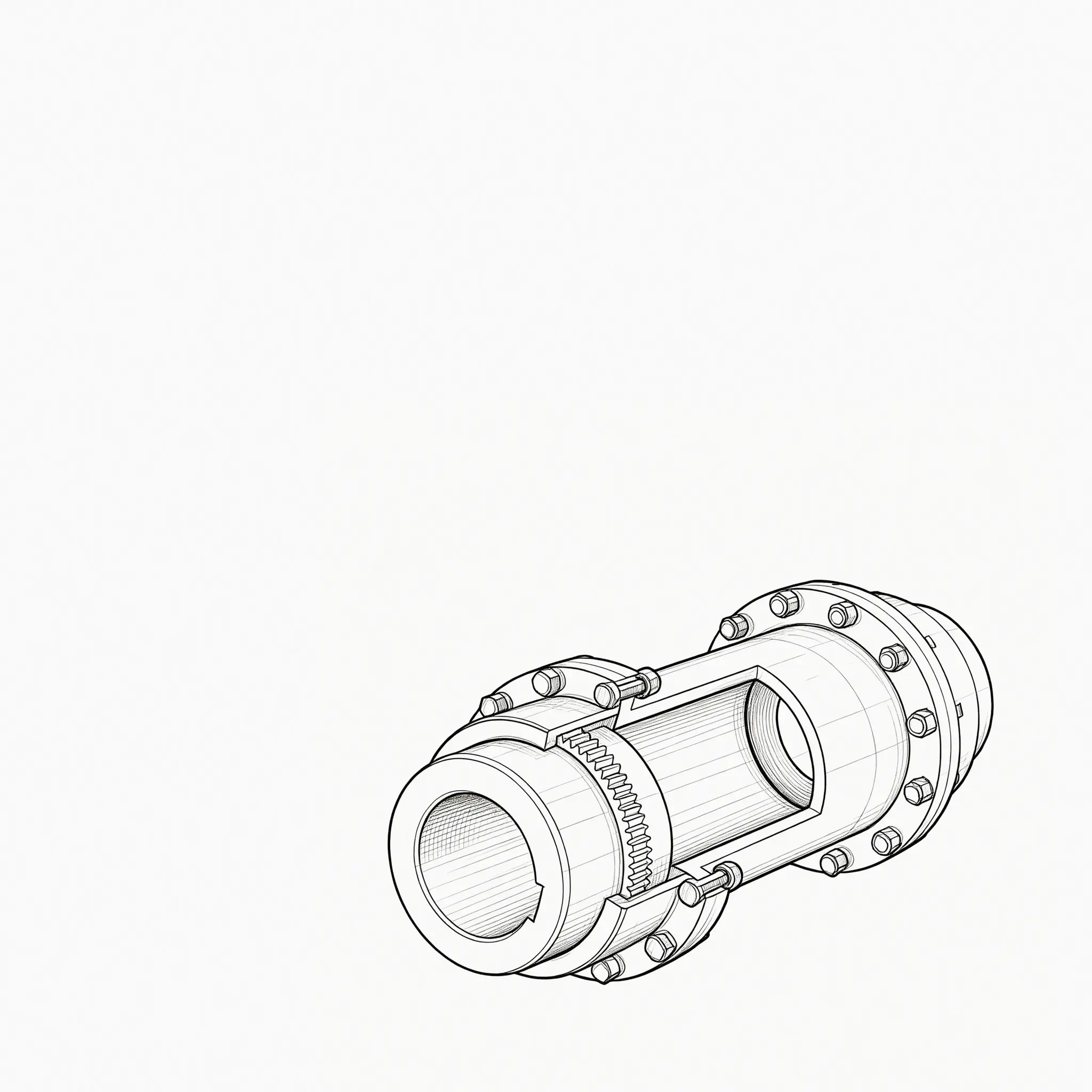
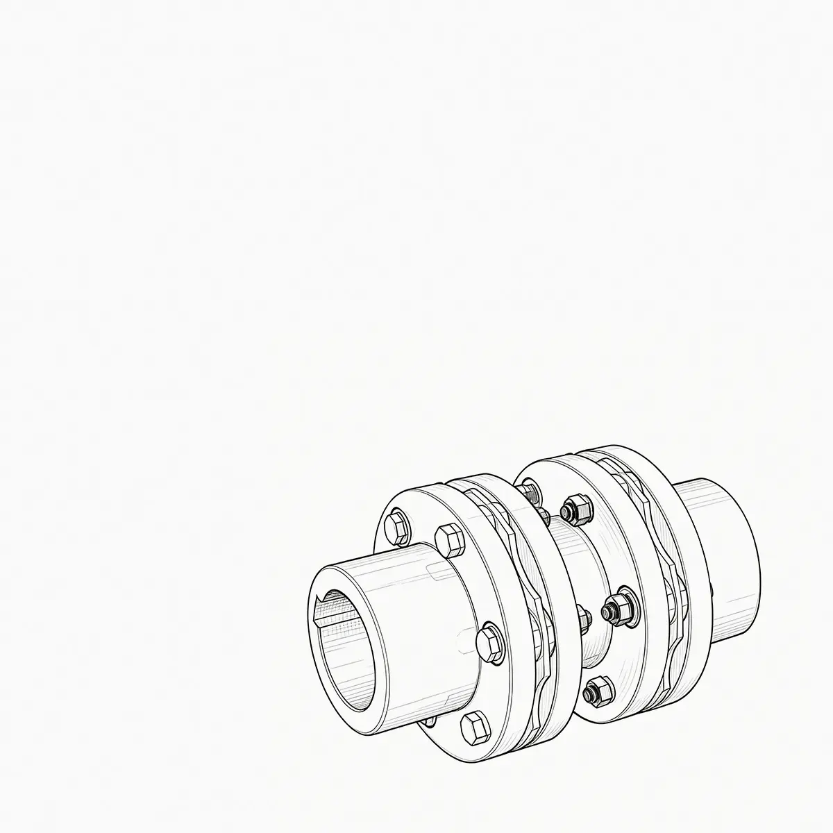
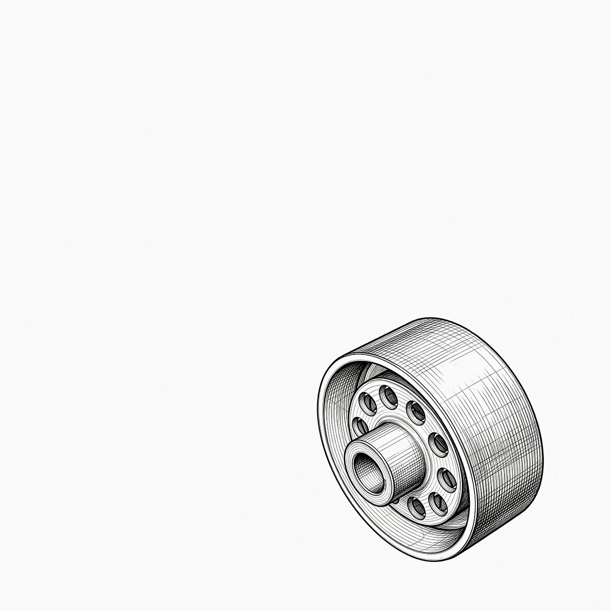
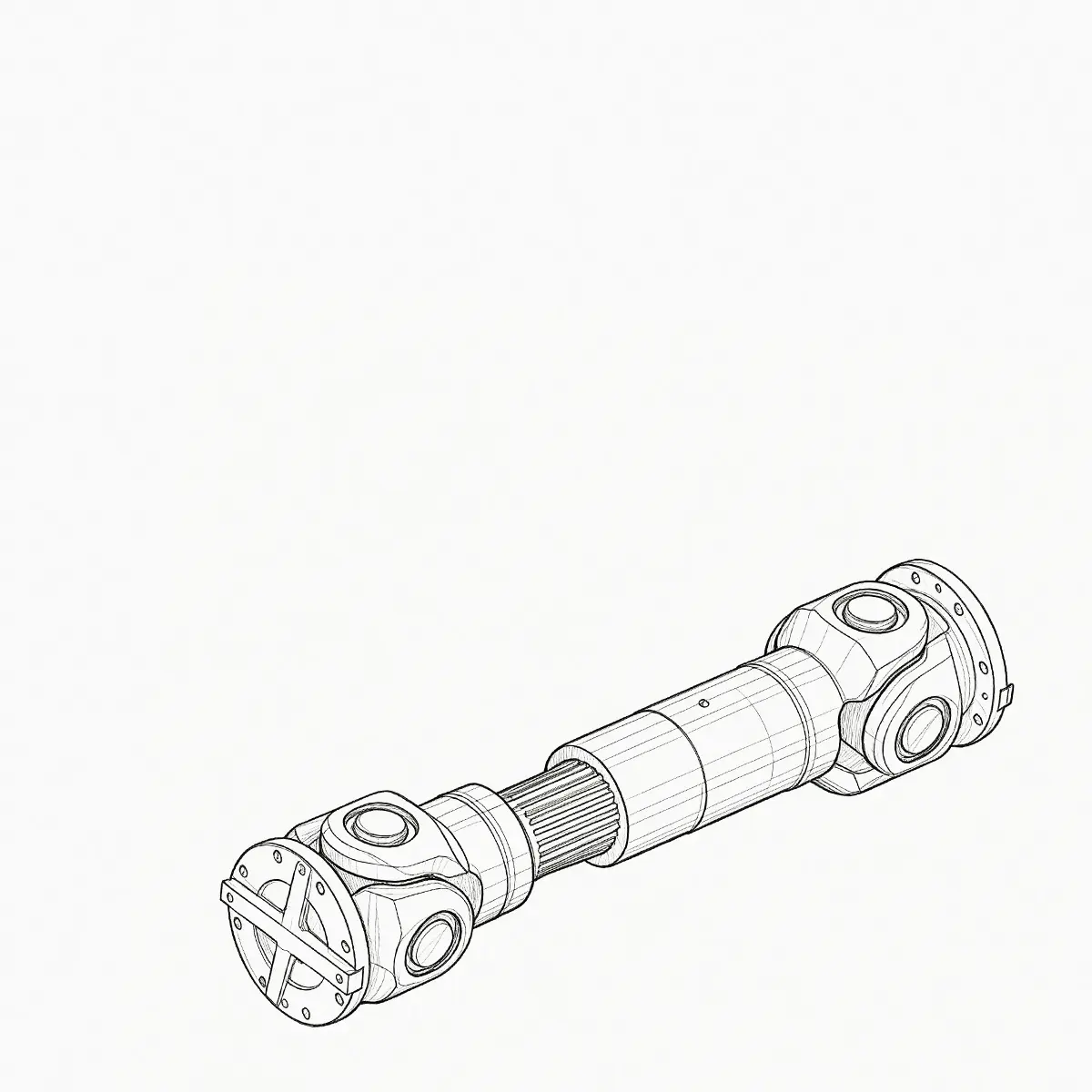

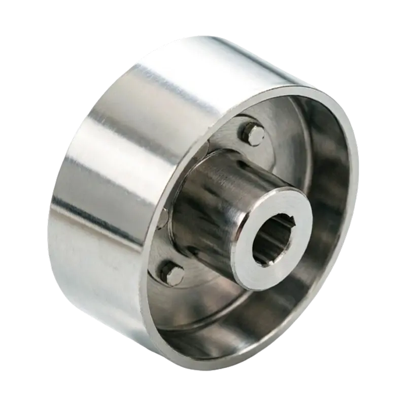
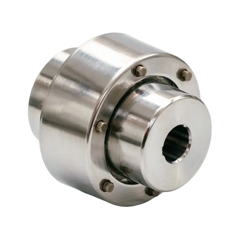
Consider a 250 kW crane hoist that begins to vibrate only when the load is lifted. The drum gear coupling is inspected ...
READ MORE
Heavy-Duty Drum Gear Couplings for High-Torque Industrial Drives
Admin 2026-09-13Content
- 1 1. The Role of a Coupling in Heavy Industrial Equipment
- 2 2. Construction of the GICL Drum Gear Coupling
- 3 3. How Crowned Teeth Improve Coupling Performance
- 4 4. Main Advantages Compared with Conventional Coupling Solutions
- 5 5. Industrial Applications
- 6 6. Engineering and Manufacturing Strengths
- 7 7. Coupling Selection Procedure
- 8 8. Installation Guidelines
- 9 9. Lubrication and Maintenance
- 10 10. Comparison with Other Coupling Categories
- 11 11. Product Advantages for OEM and Replacement Projects
- 12 12. Quality, Standards, and Documentation
- 13 13. Why Manufacturing Process Matters to Coupling Reliability
- 14 14. Application-Specific Customization
- 15 15. Q&A
- 15.1 Q1: What is a drum gear coupling?
- 15.2 Q2: What makes the GICL design different from a straight-tooth gear coupling?
- 15.3 Q3: Which industries commonly use this coupling?
- 15.4 Q4: Can the coupling compensate for axial movement?
- 15.5 Q5: Does the coupling eliminate the need for shaft alignment?
- 15.6 Q6: Is lubrication required?
- 15.7 Q7: How should the coupling be selected?
- 15.8 Q8: Can Orienthold Machinery provide customized couplings?
- 15.9 Q9: What information should be supplied for a quotation?
- 15.10 Q10: What are the main maintenance concerns?
- 15.11 Q11: Can the coupling be used in a crane or hoist?
- 15.12 Q12: Why is the manufacturer’s inspection capability important?
- 16 16. Recommended Purchasing and Project Workflow
- 17 17. Service and Support Capabilities
- 18 18. Conclusion
- 19 References
- 20 Product: GICL Type Drum-type Gear Coupling
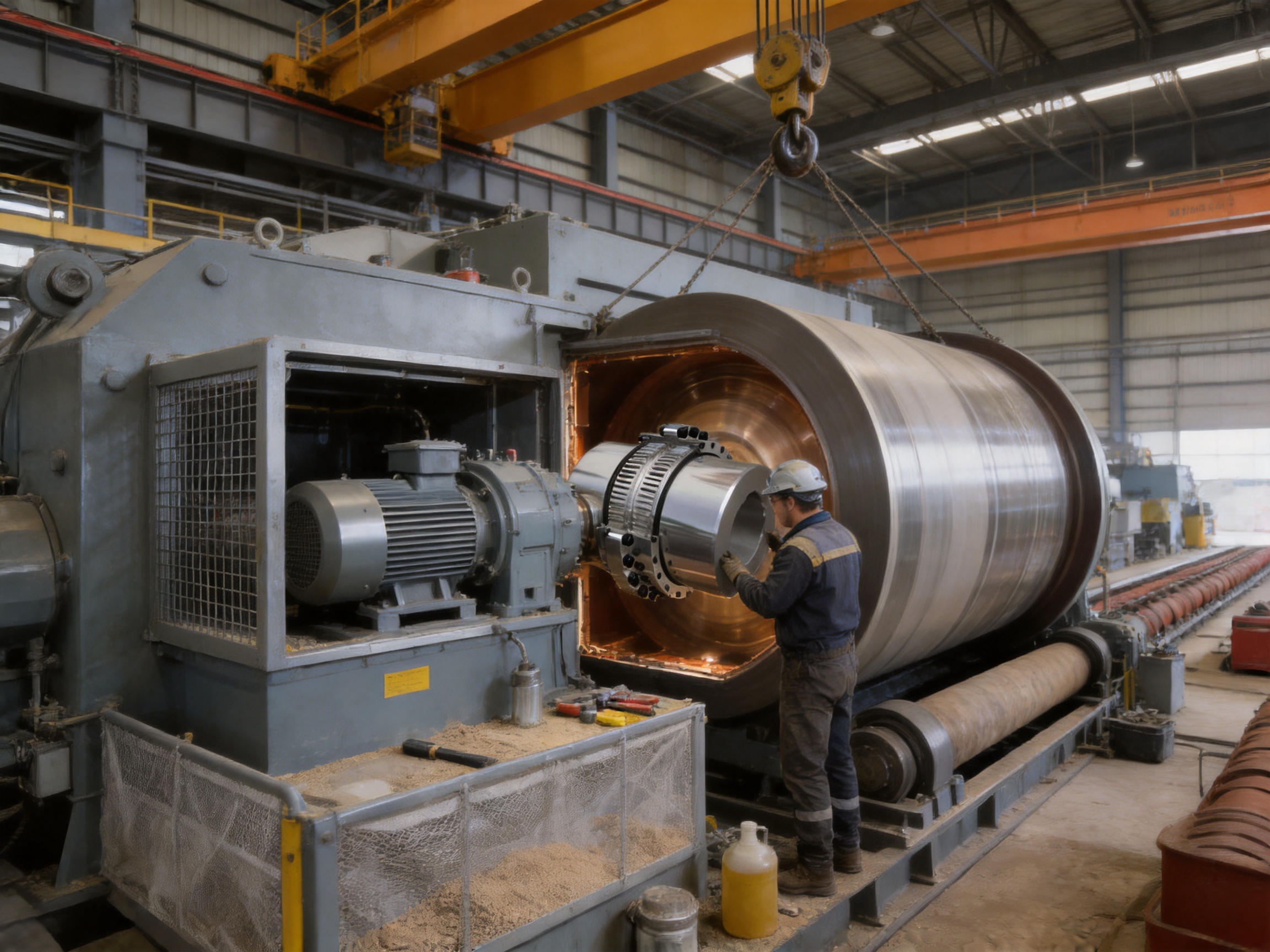
Industrial drive systems used in metallurgy, mining, lifting, transportation, construction, and heavy machinery must transmit substantial torque while operating under demanding mechanical conditions. Shafts may experience radial offset, angular deviation, axial movement, vibration, shock loading, temperature variation, and repeated starting and stopping. If these movements are not accommodated properly, the resulting stresses can damage bearings, gears, shafts, and connected machinery. A suitable coupling therefore needs to do more than connect two shafts. It must transmit torque reliably, compensate for misalignment, limit additional loads, and maintain stable performance throughout a long service life.
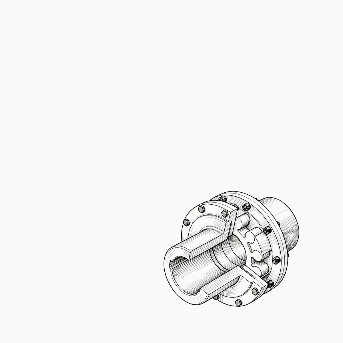
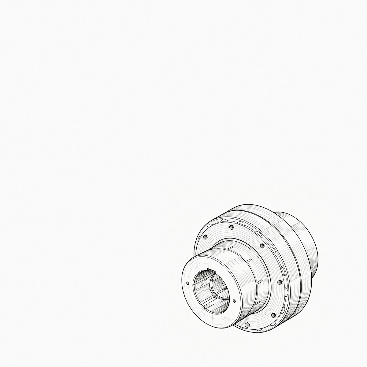
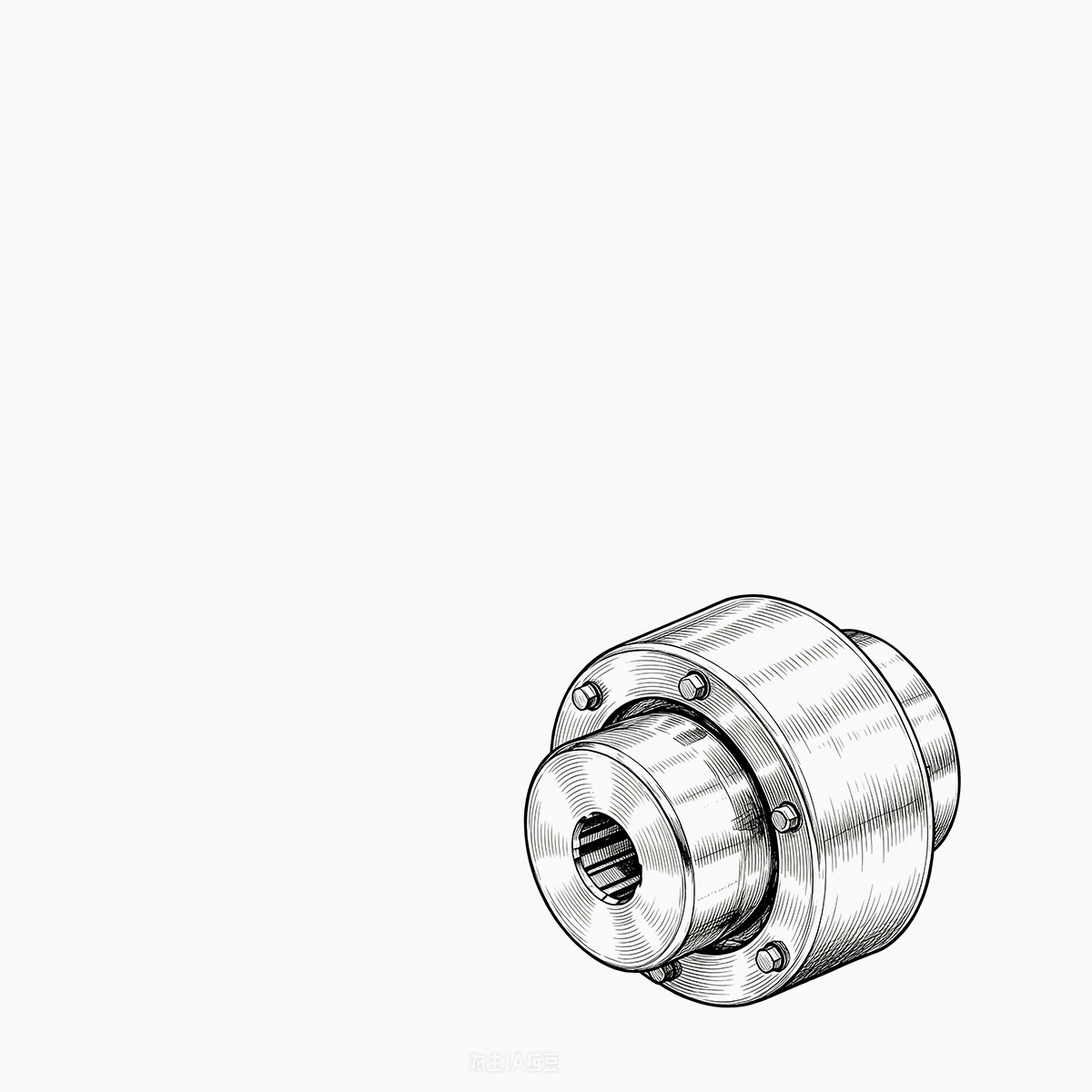
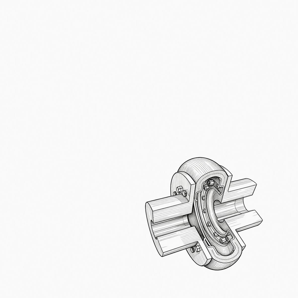
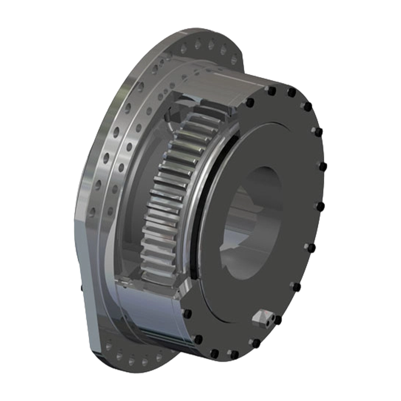
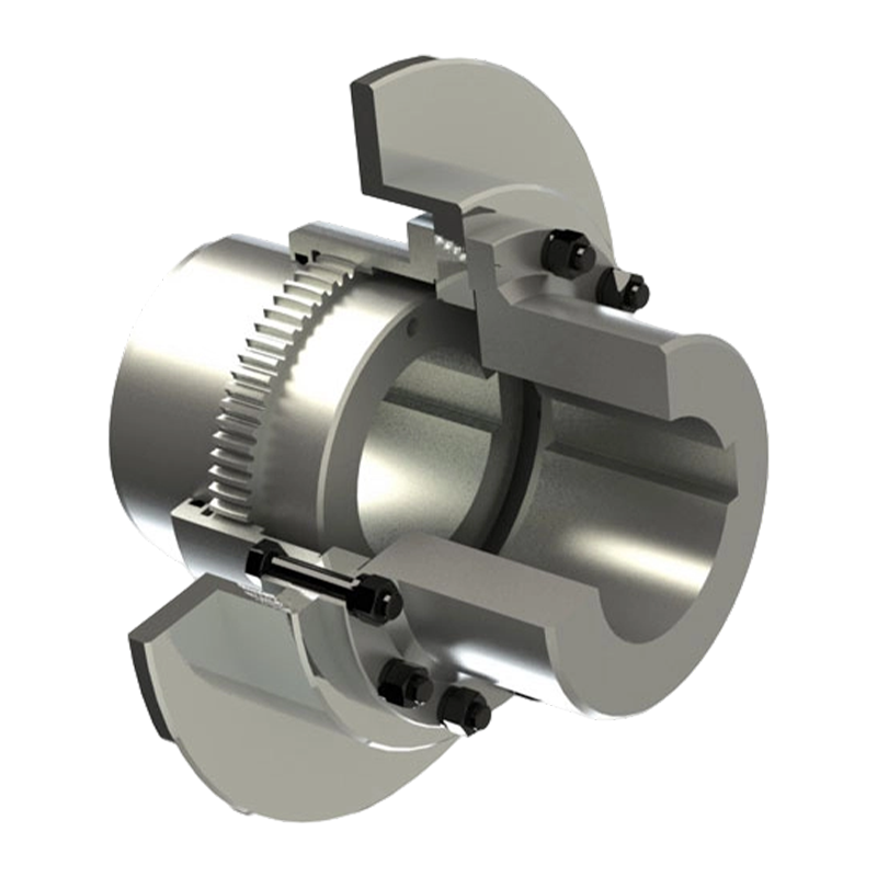
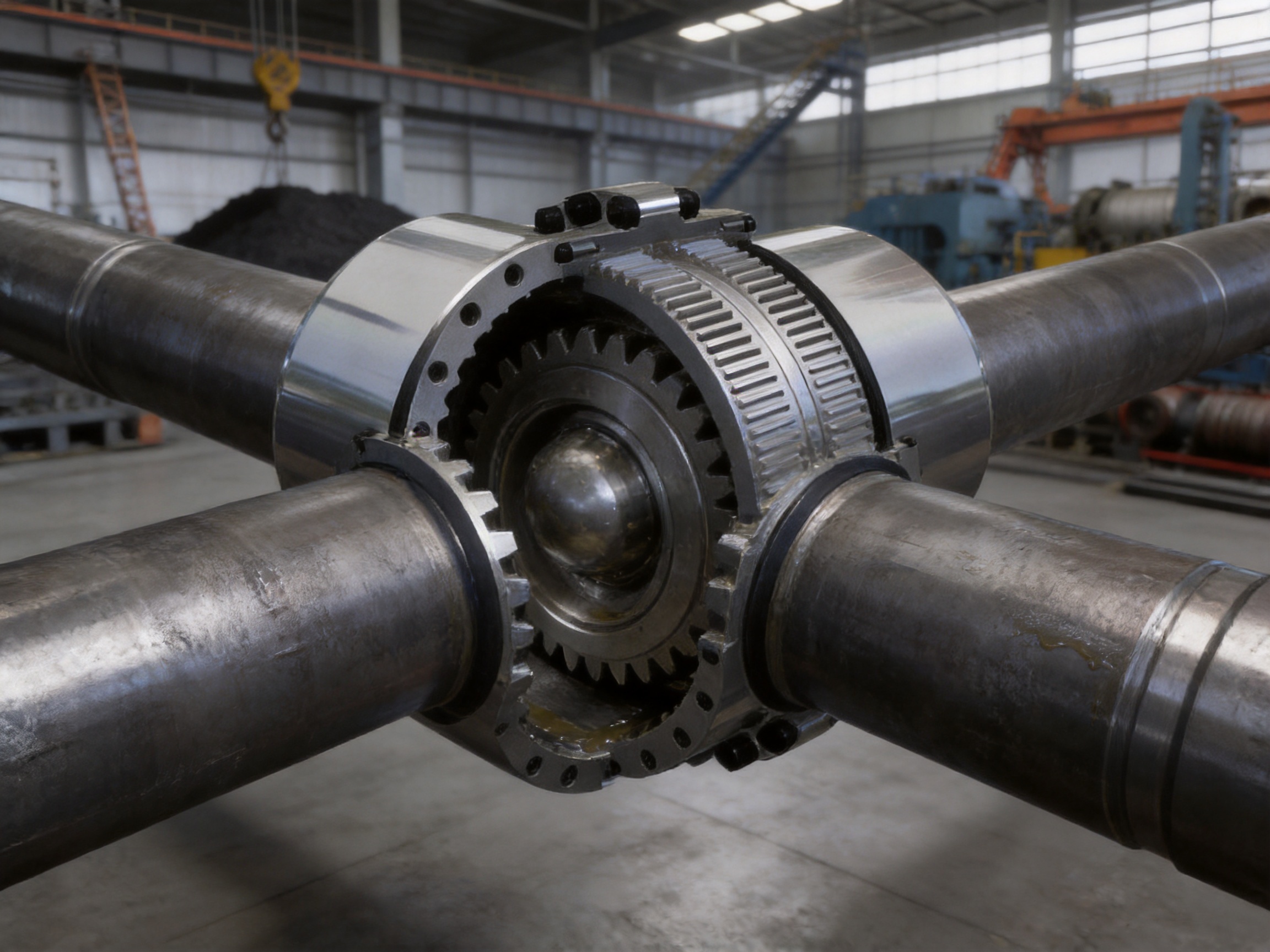
The GICL type drum-type gear coupling is designed for precisely this type of application. It is a heavy-duty power transmission component developed for low-speed, high-torque drive systems and complex operating environments. Its principal structural elements are an external-tooth sleeve and an internal gear hub. The external gear uses a crowned tooth profile rather than a conventional straight-tooth form. This geometry allows the coupling to maintain effective tooth contact when the connected shafts are not perfectly aligned or when operating deformation occurs under load.
By combining high torque capacity, misalignment compensation, compact construction, and durable gear engagement, the drum gear coupling provides a practical connection solution for equipment that cannot rely on rigid shaft alignment. It is particularly appropriate for cranes, hoisting machinery, rolling mills, conveyors, crushers, mining equipment, and other systems in which reliability and resistance to shock loads are essential.
Manufactured by Zhenjiang Orienthold Machinery Co., Ltd., the product reflects the company’s focus on coupling design, precision production, inspection, and application support. Orienthold Machinery integrates product design, manufacturing, testing, and service, enabling it to provide standard and customized coupling solutions for different shaft sizes, torque requirements, installation conditions, and industrial environments.
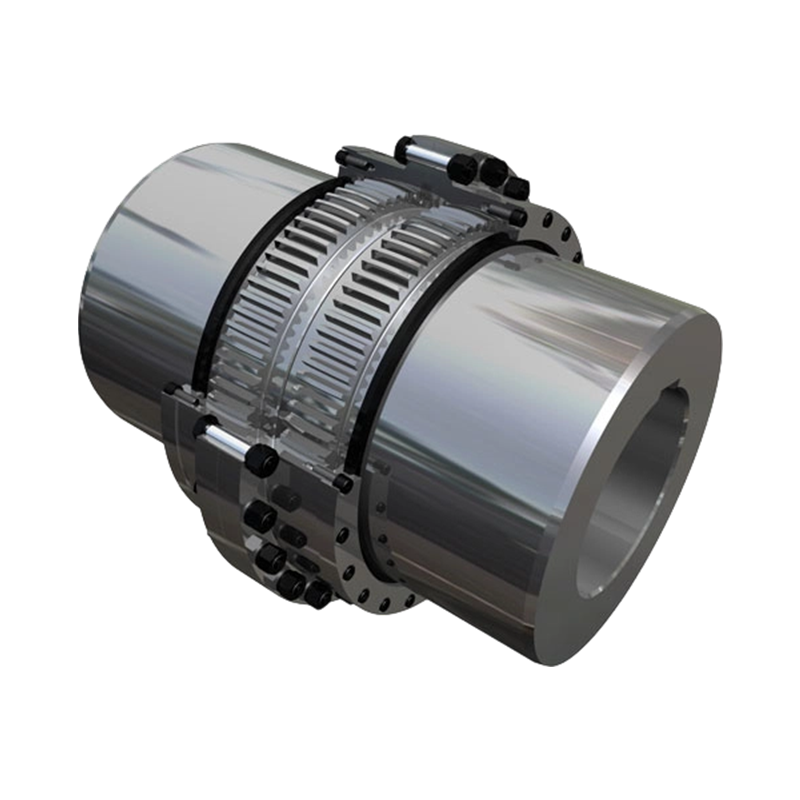
GICL Type Drum-type Gear Coupling
1. The Role of a Coupling in Heavy Industrial Equipment
A shaft coupling is installed between two shafts to transfer rotational power from a driving machine to a driven machine. In a simple drive, the coupling may appear to be a basic mechanical connector. In practice, however, it plays a critical role in protecting the complete transmission system. Even when shafts are aligned during initial installation, changes can occur after the equipment begins operating.
Foundation settlement, thermal expansion, bearing clearance, structural deflection, manufacturing tolerances, and external loads can all alter shaft alignment. In lifting and transportation machinery, the load may change suddenly as material is raised, lowered, accelerated, or stopped. In mining and crushing equipment, impact forces and vibration may be transmitted through the drive system. In metallurgical equipment, high temperatures and repeated load cycles can create additional deformation.
A rigid connection cannot easily tolerate these movements. It may transfer misalignment directly into the connected shafts and bearings, causing excessive forces and premature failure. A flexible coupling, by contrast, allows controlled movement while continuing to transmit torque. The type and amount of flexibility depend on the coupling design.
Gear couplings are commonly selected for applications that require high torque transmission in a relatively compact space. Their torque is transmitted through the engagement of external and internal gear teeth. Compared with many low-capacity flexible couplings, a gear coupling can handle larger loads and higher power levels without requiring an excessively large outside diameter.
The GICL drum gear coupling is intended for demanding installations in which the coupling must accommodate multiple types of misalignment at the same time. It provides compensation for axial, radial, and angular displacement while maintaining a positive mechanical connection between the driving and driven shafts.
1.1 Axial displacement
Axial displacement occurs when one shaft moves along its own centerline relative to the other shaft. This movement may result from thermal expansion, bearing movement, shaft float, machine-frame deformation, or changes in the position of a connected mechanism. If axial displacement is restricted by a rigid connection, the shaft system may develop additional thrust loads.
The drum gear coupling permits controlled axial movement within its designed operating range. This capability can reduce the transfer of unnecessary axial forces to bearings and other machine components. Correct selection remains important because the allowable axial movement depends on the coupling size, tooth geometry, lubrication condition, and equipment arrangement.
1.2 Radial displacement
Radial misalignment occurs when the centerlines of two connected shafts are parallel but offset from one another. It may be caused by installation tolerances, bearing wear, foundation movement, or structural deflection. Radial offset causes the coupling components to operate away from their ideal concentric position.
The crowned external teeth of the GICL coupling help maintain useful tooth engagement under radial offset. Instead of relying on contact concentrated at the edge of a straight tooth, the crowned profile allows the mating parts to articulate while continuing to transmit torque across the engaged teeth.
1.3 Angular misalignment
Angular misalignment occurs when the centerlines of the two shafts intersect or diverge at an angle. It can result from inaccurate installation, uneven mounting surfaces, shaft deflection, or movement of a connected machine. Angular misalignment is especially important in long or heavy drive systems because it can cause uneven tooth loading and additional bending forces.
The spherical form of the crowned tooth allows the coupling to accommodate angular deviation more effectively than a conventional straight-tooth connection. It helps preserve contact between the internal and external teeth while the shafts operate at a small angle relative to each other.
2. Construction of the GICL Drum Gear Coupling
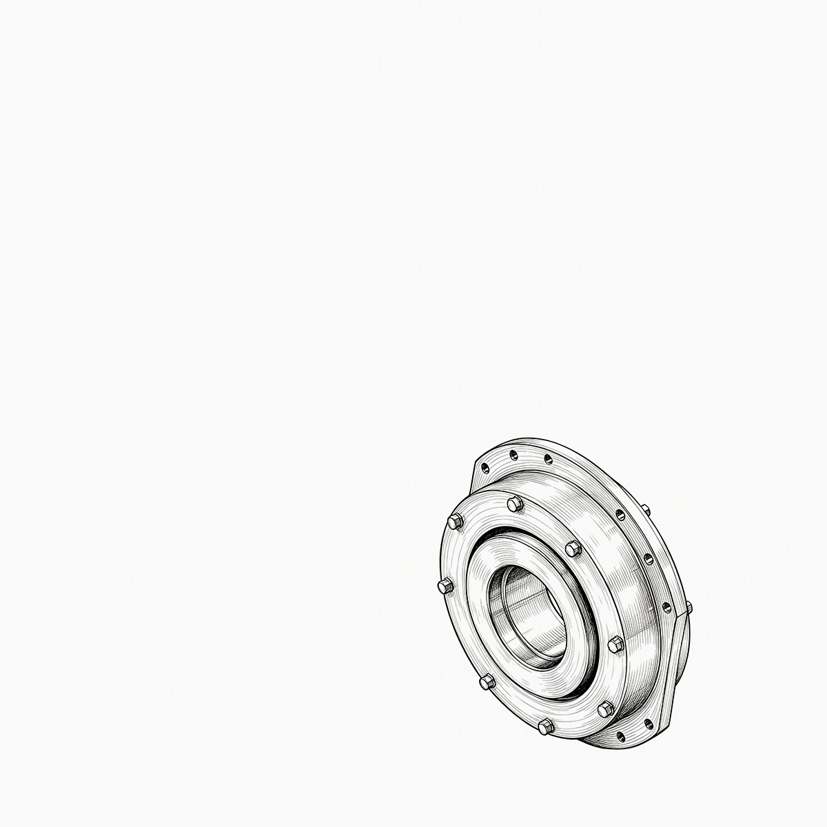
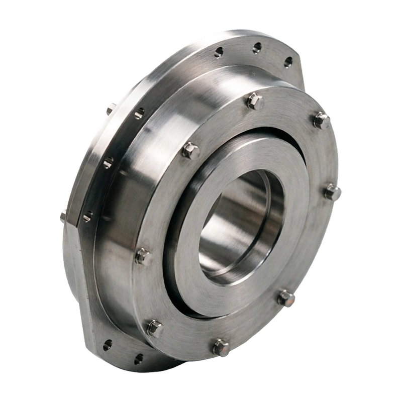
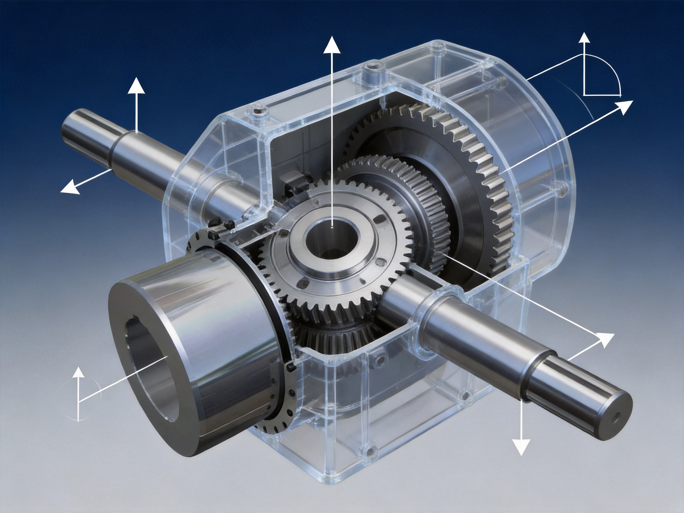
The GICL type drum gear coupling consists primarily of an internal gear hub and an external-tooth sleeve. Depending on the specific configuration, the assembly may also include end covers, seals, fasteners, lubrication provisions, and other components required for installation and protection.
The internal gear hub is mounted on the shaft of the driving or driven machine. The external-tooth sleeve surrounds the hub and engages with its teeth. Torque is transferred through the meshing tooth surfaces. The coupling’s ability to accommodate movement comes from the geometry and relative movement of these mating components.
The defining feature is the drum or crowned tooth form. The external teeth are machined with a spherical profile, with the center of the spherical surface aligned with the coupling axis. This design differs from a straight-tooth coupling, in which the tooth flanks remain substantially parallel and may experience edge loading when misalignment occurs.
With crowned teeth, the coupling can pivot through a limited angle while retaining a broader and more stable contact pattern. The profile also works together with optimized tooth side clearance. The clearance provides room for relative movement and helps prevent binding when the shafts experience axial or angular displacement.
Tooth geometry must be selected carefully. Excessive clearance can increase backlash, vibration, and impact during reversing or load changes. Insufficient clearance can restrict movement, raise friction, and cause tooth interference. A properly engineered coupling balances clearance, contact area, torque capacity, and flexibility.
The coupling housing and gear components are designed for industrial service. Their dimensions, materials, heat-treatment requirements, bore arrangements, keyways, and connection details may be adapted to the operating conditions of the equipment. This flexibility is important because heavy machinery rarely operates under identical conditions from one installation to another.
3. How Crowned Teeth Improve Coupling Performance
The crowned tooth profile is the main technical advantage of the GICL drum gear coupling. It influences contact stress, misalignment behavior, load sharing, and wear. Understanding this feature helps explain why drum gear couplings are widely used in heavy industrial transmission systems.
3.1 Improved contact during misalignment
When a straight-tooth gear coupling operates with angular or radial misalignment, contact may move toward the edge of the tooth. Edge contact reduces the effective load-bearing area and increases localized pressure. Under high torque, this condition can lead to accelerated wear, pitting, deformation, or tooth breakage.
A crowned tooth has a curved profile that allows the mating components to remain in contact as the coupling articulates. The contact does not depend on the two shafts remaining perfectly collinear. This makes the coupling more tolerant of real-world installation and operating conditions.
3.2 More even distribution of load
Torque is ideally distributed across several engaged teeth. When the contact pattern remains stable, each tooth carries a reasonable portion of the transmitted load. The crowned profile assists this condition by reducing severe concentration at a single edge or small contact zone.
More even load distribution can reduce local stress and help the coupling maintain consistent performance during acceleration, deceleration, and changing load conditions. It can also reduce the likelihood of localized surface damage, particularly in applications where shock loading occurs regularly.
3.3 Reduced stress concentration
Stress concentration is a major concern in high-torque power transmission. When force is concentrated at a sharp edge or a small area, the material experiences a higher local stress than the average calculated load would suggest. Repeated stress cycles can then initiate cracks, surface fatigue, or permanent deformation.
The crowned tooth shape is intended to improve the way forces enter and leave the tooth contact area. By avoiding an abrupt edge-loaded condition during misalignment, it can reduce damaging local stress concentration. This contributes to the coupling’s suitability for cranes, rolling equipment, hoists, and other systems exposed to frequent load changes.
3.4 Better tolerance of operating deformation
Heavy equipment does not remain perfectly rigid during operation. Shafts bend slightly, housings deform, bearings move within their clearances, and frames respond to changing loads. These movements are often small, but they can significantly affect the contact pattern of a coupling.
The drum gear design allows the coupling to maintain useful engagement despite such deformation. It does not eliminate the need for correct alignment, but it provides an additional margin of tolerance that a rigid or poorly designed connection cannot offer.
4. Main Advantages Compared with Conventional Coupling Solutions
Every coupling type has an appropriate field of application. Elastomeric couplings may be suitable for vibration damping and moderate torque. Pin-and-sleeve couplings can provide economical flexible connections. Diaphragm couplings are often selected for high-speed precision applications with controlled operating conditions. Rigid couplings may be used when alignment is extremely accurate and no relative movement is expected.
The drum gear coupling is particularly advantageous when the application combines high torque, low or moderate speed, shock loading, and substantial misalignment requirements. Its strengths are related to its positive gear engagement and robust mechanical structure.
4.1 High torque capacity in a compact structure
The coupling transmits torque through multiple gear teeth rather than through a relatively small elastomeric element or friction surface. This permits a substantial torque capacity within a compact radial envelope. Compactness can be valuable where machinery layout, guard dimensions, or shaft spacing limit the available installation space.
A smaller and properly proportioned coupling can also reduce the overhung mass placed on connected shafts. This may help simplify equipment design and reduce the demand on adjacent bearings, although the final effect must always be verified using the complete machine arrangement.
4.2 Strong performance under impact loading
Heavy industrial equipment may experience torque spikes during start-up, sudden loading, material blockage, braking, or reversing. The gear-tooth connection provides a robust path for transmitting these forces. When combined with correct material selection, heat treatment, lubrication, and safety factors, the coupling can perform reliably in applications where light-duty flexible couplings may not be appropriate.
Shock resistance does not mean that the coupling can absorb unlimited impact energy. The drive system should still include appropriate motor controls, brakes, overload protection, and torque calculations. Nevertheless, the drum gear configuration is well suited to equipment in which occasional or repeated load fluctuation is unavoidable.
4.3 Compensation for combined misalignment
Many couplings accommodate one primary form of movement effectively but become less suitable when axial, radial, and angular misalignment occur together. The GICL design is intended to compensate for all three types within its specified limits. This is useful in large machines where movement is multidirectional and difficult to eliminate completely.
Combined misalignment must be evaluated rather than treated as three independent maximum values. If axial, radial, and angular deviations occur at the same time, the actual operating condition may be more severe than any individual value suggests. Proper engineering review is therefore essential for reliable selection.
4.4 Reduced additional loads on the shaft system
When a coupling can move in response to shaft displacement, it may reduce the additional forces imposed on shafts, bearings, and gearboxes. This does not remove transmitted torque or normal reaction forces, but it can prevent misalignment from becoming an unnecessary source of bearing load and shaft bending.
Reducing these additional loads may improve the operating stability of the entire drive and help extend the service life of connected components. The result is often a system-level benefit rather than an isolated coupling benefit.
4.5 Reliable operation in heavy industrial environments
Mining, metallurgy, construction, and lifting machinery often operate in dusty, vibrating, wet, or otherwise severe conditions. The coupling must be designed and maintained as part of the complete machine. A robust gear structure, suitable sealing, correct lubricant, and appropriate protective guard can help the coupling withstand these environments.
For especially severe applications, the coupling specification should address ambient temperature, contamination, installation orientation, starting frequency, reversing cycles, braking loads, and inspection access. These factors are important when comparing a heavy-duty drum gear coupling with a more general-purpose coupling.
5. Industrial Applications
5.1 Metallurgical machinery
Metallurgical production lines contain many high-load drive systems, including rolling mills, conveyors, transfer tables, coilers, feeders, and material-handling devices. These machines may experience high torque, vibration, thermal effects, and frequent changes in operating speed or load.
A drum gear coupling can provide a strong connection between motors, gearboxes, rolls, drums, and other rotating components. Its ability to compensate for shaft movement is valuable in equipment where housings and frames are exposed to high loads and temperature variation.
5.2 Mining equipment
Mining machinery is frequently subject to impact, dust, vibration, and difficult maintenance conditions. Crushers, feeders, hoists, conveyors, winches, and screening equipment require power transmission components capable of handling demanding duty cycles.
The high torque capacity and mechanical strength of a gear coupling make it suitable for these applications. A correctly enclosed and lubricated coupling can provide dependable service while limiting the effect of alignment changes caused by foundations, structural movement, and repeated shock.
5.3 Lifting and hoisting machinery
Cranes, hoists, winches, and lifting platforms require dependable torque transmission because failure can create serious operational and safety risks. Drives may include frequent starts and stops, braking actions, reversing, and changes in lifted load.
The GICL coupling is especially relevant to crane drum and hoisting applications. It can connect motors, reducers, drums, and other drive elements while accommodating the shaft movements that arise from frame deflection and load variation. Coupling selection must be coordinated with brake torque, motor starting torque, emergency stop conditions, and applicable lifting-equipment requirements.
5.4 Transportation and conveying systems
Large conveyors and transportation systems may use long shafts, multiple gearboxes, drive drums, and transfer mechanisms. Alignment can change because of foundation settlement, thermal movement, or structural loading. A flexible high-torque connection can help maintain stable operation while reducing the transfer of unwanted forces between machine sections.
In conveyors handling bulk materials, the drive may also experience start-up resistance, material accumulation, and sudden changes in load. The coupling should therefore be selected using service factors that reflect the actual operating cycle rather than only the nominal motor rating.
5.5 Construction and heavy machinery
Construction machinery often operates in changing locations and under variable loads. Hoisting systems, winches, mixers, crushers, and large mobile or semi-mobile equipment can benefit from a coupling that tolerates installation variation and dynamic loading.
In these applications, accessibility and maintenance are also important. The coupling arrangement should allow inspection, lubrication, removal, and replacement without requiring excessive disassembly of the machine.
6. Engineering and Manufacturing Strengths
The performance of a heavy-duty coupling depends on more than its basic design. Material quality, machining accuracy, heat treatment, assembly control, inspection, and service support all affect final reliability. Zhenjiang Orienthold Machinery Co., Ltd. integrates design, production, and service within its coupling manufacturing operation.
6.1 Integrated product development
An integrated manufacturing organization can coordinate engineering design with production capabilities and inspection requirements. This helps ensure that the selected tooth geometry, shaft arrangement, housing dimensions, and material specifications are practical to manufacture and verify.
For customers with nonstandard requirements, an integrated approach also simplifies communication. Technical information about torque, speed, shaft dimensions, installation space, environmental conditions, and duty cycle can be reviewed by the same organization that produces the coupling.
6.2 Advanced production equipment
Precision gear couplings require controlled machining of tooth profiles, bores, keyways, shoulders, mounting surfaces, and sealing areas. Advanced production equipment helps maintain dimensional consistency and repeatability across batches.
For the GICL coupling, the accuracy of the crowned tooth profile is particularly important. The tooth curvature, pitch, clearance, surface finish, and concentricity must work together to produce the intended contact pattern. Appropriate machining equipment and process controls support these requirements.
6.3 Material and heat-treatment control
Gear coupling components must resist tooth wear, surface fatigue, deformation, and repeated impact. Material selection depends on coupling size, torque, speed, duty cycle, environmental conditions, and manufacturing method. Heat treatment may be applied to improve surface hardness, strength, toughness, or wear resistance.
Heat treatment should be controlled carefully. Excessive hardness without sufficient toughness may make a component vulnerable to impact damage, while inadequate hardness may accelerate tooth wear. The correct balance is determined by the component’s function and the complete application.
6.4 Dimensional inspection
Inspection is essential for verifying whether manufactured components meet design requirements. Typical checks may include bore dimensions, keyway size, tooth dimensions, concentricity, runout, face alignment, surface condition, and assembly fit.
Inspection equipment and documented procedures help identify deviations before the coupling is delivered. This is particularly valuable for high-capacity couplings because small dimensional errors can influence load distribution and installation behavior.
6.5 Testing and quality supervision
Orienthold Machinery operates under a quality supervision system supported by inspection and testing equipment. The company states that its products comply with applicable national standards and that it maintains complete testing methods for its manufacturing activities.
Quality supervision should cover incoming materials, machining operations, heat treatment, surface finishing, assembly, final inspection, packaging, and delivery documentation. A complete process reduces the possibility that a component will meet an isolated dimensional requirement but fail to perform reliably as part of the assembled coupling.
6.6 Custom engineering support
Industrial couplings often require customization. The customer may need a special bore, keyway, flange, brake drum, spacer, mounting arrangement, corrosion-resistant finish, or modified length. The coupling may also need to fit an existing gearbox or shaft without changing the surrounding machinery.
Orienthold Machinery provides customization and one-stop technical services intended to address these needs. Early communication is recommended because a coupling should be designed around the complete drive system rather than selected only by nominal shaft diameter.
7. Coupling Selection Procedure
Selecting the correct drum gear coupling requires more information than motor power alone. A systematic review helps avoid undersizing, excessive flexibility, inadequate lubrication, or installation problems.
7.1 Determine the transmitted torque
Begin with the rated power and operating speed of the drive. The nominal torque can be calculated from the power and rotational speed, using the appropriate unit conversion. The coupling should then be selected using a service factor that reflects the machine type and operating conditions.
Starting torque, braking torque, reversing torque, shock loading, load fluctuations, and the number of starts per hour should be considered. A crusher, crane hoist, and continuously running conveyor may have the same motor power but very different coupling requirements.
7.2 Evaluate speed and balance requirements
The coupling’s maximum operating speed must exceed the actual working speed with an appropriate margin. At higher speeds, balancing, runout, concentricity, and guard design become increasingly important. Although drum gear couplings are commonly associated with low-speed and high-torque equipment, the specific allowable speed depends on the coupling size and configuration.
7.3 Measure the shafts and available space
Important dimensional information includes shaft diameters, keyway dimensions, shaft extensions, distance between shaft ends, coupling outside diameter, total length, and available radial clearance. The coupling must also be compatible with the mounting method and the ability to assemble or remove it in the field.
Incorrect shaft measurements can result in loose fits, interference, insufficient key engagement, or excessive machining after delivery. Shaft and coupling dimensions should therefore be checked against engineering drawings before production.
7.4 Calculate expected misalignment
Radial, angular, and axial movement should be estimated under both static and operating conditions. The analysis should include thermal growth, foundation movement, shaft deflection, bearing clearance, and machine-frame deformation.
The coupling should not be used as a substitute for proper installation. Misalignment compensation is a design capability, not permission to ignore alignment procedures. Excessive displacement can still produce high forces, rapid wear, and reduced service life.
7.5 Consider the environment
Dust, water, chemicals, high temperature, low temperature, vibration, and outdoor exposure may influence the required seals, lubricant, surface treatment, and maintenance interval. Applications near molten metal, abrasive material, or corrosive chemicals require particularly careful specification.
The customer should provide information about ambient conditions and contamination risks. This allows the manufacturer to recommend suitable protection and maintenance practices.
7.6 Review safety and maintenance requirements
The coupling must be protected by a suitable guard to prevent contact with rotating parts and to contain lubricant or damaged components if a failure occurs. The guard should also allow reasonable access for inspection and maintenance.
Maintenance requirements should be considered during layout design. If the coupling is difficult to access, lubrication and inspection may be neglected. A technically suitable coupling can still experience reduced service life if the installation does not support practical maintenance.
8. Installation Guidelines
Correct installation is essential for achieving the benefits of a crowned-tooth gear coupling. Before installation, check the coupling components for damage, contamination, corrosion, and dimensional conformity. Confirm that the shafts, keyways, keys, fasteners, seals, and lubricant are compatible with the approved specification.
The shaft ends should be cleaned and inspected. Burrs, raised material, or surface damage should be removed carefully without changing the intended dimensions. Hubs should be installed using approved methods. Excessive hammering can damage gear teeth, bearings, or shaft shoulders and should be avoided.
Initial shaft alignment should be performed according to the equipment manufacturer’s requirements. Dial indicators, laser alignment tools, or other suitable instruments may be used. The alignment target should account for operating conditions such as thermal growth and expected shaft movement.
After the hubs and sleeves are installed, verify that the external and internal teeth engage correctly. Check axial position, end clearances, fastener tightness, seal installation, and lubrication. The coupling should rotate freely by hand when practical and should not show binding or abnormal resistance.
Once the machine is started, observe vibration, temperature, noise, lubricant leakage, and operating behavior. A gradual commissioning process can help identify installation issues before the coupling is exposed to full load. Any unusual condition should be investigated promptly.
9. Lubrication and Maintenance
Gear couplings depend on proper lubrication because the teeth experience sliding and rolling contact as the shafts rotate and articulate. Lubrication reduces friction, limits wear, helps dissipate heat, and protects metal surfaces from corrosion and contamination.
The lubricant type should be selected according to the coupling design, operating speed, load, ambient temperature, and manufacturer’s instructions. An unsuitable lubricant may separate, harden, leak, or fail to provide adequate film strength. Mixing incompatible lubricants should be avoided.
Inspection intervals should reflect the severity of service. Heavy shock, high temperature, frequent starts, outdoor exposure, and contaminated environments generally require more frequent inspection. During inspection, examine seals, fasteners, housing condition, lubricant condition, tooth wear, and signs of overheating.
Tooth wear may appear as polishing, pitting, scoring, flaking, or uneven contact. Uneven wear can indicate misalignment, inadequate lubrication, excessive clearance, overload, or a damaged component. Finding and correcting the cause is more important than simply replacing lubricant or individual parts.
Maintenance records should include installation date, coupling identification, lubricant type, inspection findings, corrective actions, and replacement components. These records can reveal changes in operating conditions and help establish a preventive maintenance schedule.
10. Comparison with Other Coupling Categories
| Coupling type | Typical strength | Common limitation | Reason to consider a drum gear coupling |
|---|---|---|---|
| Drum gear coupling | High torque, combined misalignment compensation, strong resistance to heavy-duty loading | Requires lubrication, sealing, inspection, and proper alignment | Suitable for low-speed, high-torque equipment with shock loads and shaft movement |
| Diaphragm coupling | High-speed operation and low-backlash transmission | May be less suitable for severe shock loading and large displacement in heavy machinery | Offers a more robust gear-based solution for heavy industrial torque transmission |
| Elastic sleeve pin coupling | Simple construction and vibration damping | Elastomeric elements may have temperature, aging, and torque limitations | Provides greater mechanical load capacity where flexible rubber elements are insufficient |
| Cross universal coupling | Accommodates significant angular movement in selected arrangements | May require more space and specialized maintenance | Provides a compact shaft connection for applications requiring gear engagement |
| Plum elastic coupling | Compact size, vibration isolation, and easy replacement of the elastic element | Capacity and environmental resistance depend on the elastomer | Better suited to severe high-torque and impact conditions where an elastomer may be overloaded |
| Tire coupling | Strong vibration and shock absorption | Rubber tire condition, temperature, and aging affect performance | Offers a positive mechanical transmission path with high torque density |
This comparison does not mean that one coupling category is universally superior. The correct choice depends on the machine’s speed, torque, misalignment, environment, vibration requirements, maintenance capability, and safety conditions. The advantage of the GICL drum gear coupling is its combination of heavy-duty torque capacity and multi-directional misalignment compensation.
11. Product Advantages for OEM and Replacement Projects
For original equipment manufacturers, coupling dimensions and installation interfaces must be coordinated with the entire machine. A coupling supplier that can support design, production, inspection, and customization can help reduce coordination between multiple vendors.
For replacement projects, the existing coupling may have been installed for many years, and the original drawing may no longer be available. In that situation, measurements of the shaft, hub, sleeve, keyway, flange, and installation space are necessary. Operating data should also be reviewed because the machine may now be carrying a different load or running under a changed duty cycle.
Orienthold Machinery’s coupling experience allows it to support both standard product supply and customized replacement requirements. The company’s service approach includes pre-sales consultation, technical communication, flexible logistics and payment arrangements, and maintenance support after delivery.
A replacement coupling should not be selected solely by matching the outside appearance of the old part. The original failure mode should be identified. If the old coupling failed because of overload, misalignment, insufficient lubrication, contamination, or incorrect installation, simply installing a visually identical replacement may reproduce the problem.
12. Quality, Standards, and Documentation
Industrial customers often require documentation for traceability and project approval. Depending on the application, useful documents may include product drawings, material certificates, dimensional inspection records, heat-treatment information, balancing records, assembly instructions, lubrication recommendations, and maintenance guidelines.
Compliance with applicable national standards provides a framework for dimensions, materials, performance, and inspection. However, the project specification may also impose additional requirements. Customers should identify required standards, certificates, testing procedures, and acceptance criteria before production begins.
A clear technical document should state the coupling model, size, bore dimensions, keyway details, rated torque, maximum speed, allowable misalignment, lubricant requirements, environmental limitations, and installation conditions. This information helps ensure that the supplied coupling is correctly integrated into the drive system.
Orienthold Machinery emphasizes strict quality supervision and comprehensive inspection and testing methods. These practices support consistent production and help customers evaluate whether the coupling is suitable for demanding industrial service.
13. Why Manufacturing Process Matters to Coupling Reliability
Coupling reliability is determined by the interaction of design and manufacturing. A theoretically effective tooth profile can perform poorly if the profile is inaccurate, the bore is eccentric, the material is inconsistent, or the heat treatment is uncontrolled.
Machining accuracy influences how the teeth share the transmitted load. If pitch or concentricity varies excessively, some teeth may engage earlier or carry more force than others. This can increase vibration and localized wear. Accurate finishing of the tooth surfaces helps preserve the intended contact pattern.
Assembly quality is equally important. Seals must be installed without damage, fasteners must be tightened correctly, and the sleeve and hub must be positioned according to the drawing. Poor assembly can create leakage, interference, or insufficient tooth engagement even when all individual parts meet their dimensions.
Inspection provides feedback to the production process. It can identify trends in machining, tool wear, heat treatment, or assembly that might otherwise remain unnoticed. A manufacturer with complete production and inspection capabilities is better positioned to control these variables over repeated orders.
Orienthold Machinery combines technical design, manufacturing equipment, and quality testing within its business structure. This supports the production of industrial couplings for transportation, metallurgy, chemical engineering, mining, construction, and hoisting applications.
14. Application-Specific Customization
Although the GICL type is a standardized product category, practical installations may require modifications. Customization may involve bore size, keyway form, hub length, sleeve length, flange configuration, mounting holes, sealing arrangement, surface protection, or connection to a specialized brake or drum assembly.
For applications with high starting torque, frequent reversing, or severe impact, the manufacturer may need to review the tooth capacity and service factor in greater detail. For installations with limited space, the coupling may need a different configuration while maintaining required torque and misalignment performance.
Temperature and contamination may also influence customization. High-temperature environments can affect lubricant selection and seal materials. Dusty or wet environments may require improved sealing and more frequent maintenance access. Corrosive surroundings may require special surface treatment or material consideration.
Customers should provide complete operating information during the quotation and design stage. Important data includes motor power, speed, torque, shaft diameter, shaft extension, distance between shaft ends, misalignment, duty cycle, ambient temperature, operating environment, braking conditions, and available installation space.
15. Q&A
Q1: What is a drum gear coupling?
A drum gear coupling is a flexible mechanical coupling that transmits torque through the engagement of an internal gear hub and an external-tooth sleeve. Its external teeth use a crowned or spherical profile, allowing the coupling to accommodate controlled axial, radial, and angular misalignment while maintaining gear contact.
Q2: What makes the GICL design different from a straight-tooth gear coupling?
The GICL design uses crowned external teeth. The curved tooth profile helps maintain contact when the connected shafts are offset or angled. It can reduce edge loading, improve load distribution, and lower localized stress compared with a conventional straight-tooth arrangement operating under the same misalignment condition.
Q3: Which industries commonly use this coupling?
Typical industries include metallurgy, mining, lifting and transportation, construction, material handling, heavy machinery, and industrial manufacturing. It is suitable for equipment such as cranes, hoists, rolling machinery, conveyors, crushers, feeders, winches, and drive drums.
Q4: Can the coupling compensate for axial movement?
Yes. The coupling is designed to accommodate controlled axial displacement within its specified operating range. This can help reduce additional axial loads caused by thermal expansion, shaft float, or machine-frame movement. The actual allowable displacement must be confirmed for the selected size and arrangement.
Q5: Does the coupling eliminate the need for shaft alignment?
No. A flexible coupling compensates for expected operating movement, but it should not be used to correct excessive installation error. Proper initial alignment is necessary to reduce tooth wear, vibration, bearing loads, and maintenance requirements.
Q6: Is lubrication required?
Yes. Gear tooth contact normally requires suitable lubrication to reduce friction and wear and to protect the surfaces. The lubricant type, quantity, sealing arrangement, and replacement interval should follow the approved technical instructions for the specific coupling.
Q7: How should the coupling be selected?
Selection should consider transmitted torque, motor power, operating speed, starting and braking loads, shock loading, shaft dimensions, bore and keyway requirements, axial movement, radial and angular misalignment, environmental conditions, installation space, and maintenance access. A service factor should be applied according to the machine duty.
Q8: Can Orienthold Machinery provide customized couplings?
Yes. The company provides coupling design, production, and customization services. Custom options may include special bore sizes, keyways, dimensions, mounting interfaces, sealing arrangements, and other details required for OEM or replacement installations.
Q9: What information should be supplied for a quotation?
Customers should provide the machine type, motor power, speed, torque if available, shaft diameters, shaft extensions, distance between shaft ends, keyway information, expected misalignment, operating temperature, environmental conditions, starting frequency, braking or reversing requirements, and dimensional drawings or photographs when available.
Q10: What are the main maintenance concerns?
The main concerns are lubricant condition, sealing performance, tooth wear, fastener tightness, vibration, temperature, and alignment. Periodic inspections should be more frequent in applications involving shock loads, dust, water, high temperature, frequent reversing, or heavy operating cycles.
Q11: Can the coupling be used in a crane or hoist?
It can be suitable for crane and hoist drives when the size, torque rating, speed, braking load, misalignment, and safety requirements are correctly evaluated. Lifting applications require careful engineering because emergency stops, suspended loads, and dynamic factors may create loads above normal running torque.
Q12: Why is the manufacturer’s inspection capability important?
Gear couplings rely on accurate tooth geometry, concentricity, bore dimensions, material properties, heat treatment, and assembly quality. Comprehensive inspection helps verify these characteristics and supports consistent performance across production batches.
16. Recommended Purchasing and Project Workflow
A reliable purchasing process begins with a clear application review. The equipment manufacturer or end user should identify the driving and driven machines, expected operating cycle, load characteristics, environmental conditions, and installation limitations.
The next step is to prepare dimensional information. Shaft diameters, keyways, shaft extensions, distance between shaft ends, mounting space, and guard dimensions should be verified. If the coupling is replacing an existing model, measurements should be taken directly from the equipment rather than copied from assumptions.
The manufacturer can then recommend a coupling size and configuration. The selection should be checked against torque, speed, service factor, misalignment, lubrication, and environmental requirements. Where necessary, an engineering drawing should be approved before production.
Before shipment, customers may request inspection documents, material information, dimensional reports, assembly instructions, and maintenance recommendations. Upon delivery, all components should be checked against the approved drawing and packing list.
After installation, the customer should record alignment results, lubricant details, commissioning observations, and initial operating conditions. This information creates a useful baseline for future maintenance and helps identify changes over time.
17. Service and Support Capabilities
Orienthold Machinery is a medium-sized enterprise specializing in couplings and papermaking machinery. Its business integrates design, production, and service, allowing it to support customers from initial consultation through delivery and maintenance.
The company serves customers in transportation, metallurgy, chemical engineering, mining, construction, hoisting, and related industries. Its products are supplied to large enterprises in different markets, where consistent quality, technical communication, and delivery coordination are important purchasing considerations.
Pre-sales support can include application analysis, product selection, drawing review, customization discussion, and quotation preparation. During production, technical information can be coordinated with manufacturing and inspection requirements. After delivery, the company can provide guidance related to installation, maintenance, replacement, and service support.
Flexible logistics and payment arrangements may also be useful for international industrial projects. However, delivery planning should be coordinated with production schedules, inspection requirements, export documentation, packaging, and the customer’s site installation timetable.
For technical inquiries, customers may contact Zhenjiang Orienthold Machinery Co., Ltd. by telephone at +86-18652865511 or by email at sales@ohmach.com. The company is located at No. 1, Minying Developing Zone, Zhenjiang, Jiangsu, China.
18. Conclusion
The GICL type drum gear coupling is designed for the demanding requirements of low-speed, high-torque industrial transmission. Its internal gear hub and external-tooth sleeve create a strong mechanical connection, while the crowned external teeth help maintain contact under controlled axial, radial, and angular misalignment.
Compared with less robust coupling solutions, the drum gear configuration offers important advantages for heavy machinery: high torque density, tolerance of operating deformation, improved load distribution, reduced edge loading, and dependable performance under impact and variable loads. These characteristics make it suitable for metallurgy, mining, cranes, hoists, conveyors, crushers, transportation equipment, and other industrial drives.
The product’s final performance depends on correct sizing, accurate shaft measurements, proper alignment, suitable lubrication, effective sealing, and regular inspection. Manufacturing quality is equally important. Precision machining, material control, heat treatment, dimensional inspection, assembly supervision, and documented testing all contribute to coupling reliability.
Zhenjiang Orienthold Machinery Co., Ltd. combines coupling design, manufacturing, testing, customization, and service. This integrated capability enables the company to support both standard orders and application-specific projects. For equipment operators and OEMs seeking a robust connection for high-torque machinery, a properly selected and maintained GICL drum gear coupling can provide a durable foundation for stable power transmission and longer system service life.
References
1. Industrial Power Transmission Coupling Engineering Principles, technical reference literature.
2. Gear Coupling Design, Lubrication, and Maintenance Practices, engineering handbook.
3. Flexible Shaft Coupling Selection for Heavy Machinery, mechanical transmission reference.
4. Industrial Gear Design and Tooth Contact Analysis, power transmission engineering text.
5. Machinery Alignment, Shaft Deflection, and Bearing Load Considerations, maintenance engineering guide.
6. Heavy-Duty Hoisting and Material-Handling Drive Systems, industrial equipment reference.
7. National and International Standards Relating to Industrial Couplings, gear components, and mechanical power transmission.
8. Manufacturer’s product information and technical data for GICL type drum gear couplings.
Product: GICL Type Drum-type Gear Coupling
PREV: JMII Double-Diaphragm Coupling: Precision Torque Transmission for Demanding Industrial SystemsNEXT: JMII Double-Diaphragm Coupling: Precision Torque Transmission for Demanding Industrial Systems
Be the First to Know
For exclusive deals and latest offers, sign up by entering your email address below.
Related products
News
-
-
Gear Coupling vs. Drum Gear Coupling: The Core Difference The main difference is that "gear coupling" is a broad catego...
READ MORE -
Industrial Couplings: The Definitive Technical Encyclopedia – Classification, Sizing, Failure Prevention, and Lifecycle...
READ MORE -
Two quotes land for the same replacement gear coupling: $1,850 from one shop and $2,600 from another. Both promise stan...
READ MORE -
A mill drive rarely fails without warning. It knocks at speed, throws a smear of dark grease around the sleeve flange, ...
READ MORE -
China's coupling industry is at a critical historical juncture of transformation from scale expansion to quality and eff...
READ MORE


ABOUT US
PRODUCTS
INDUSTRIES
CONTACT US
- Phone: +86-18652865511
- Email: sales@ohmach.com
- Address: No.1, Minying Developing Zone, Zhenjiang, Jiangsu, China
Copyright Zhenjiang Orienthold Machinery Co., Ltd. All Rights Reserved.
 Custom Industrial Shaft Coupling Manufacturers