 English
 русский
 Português
 عربى
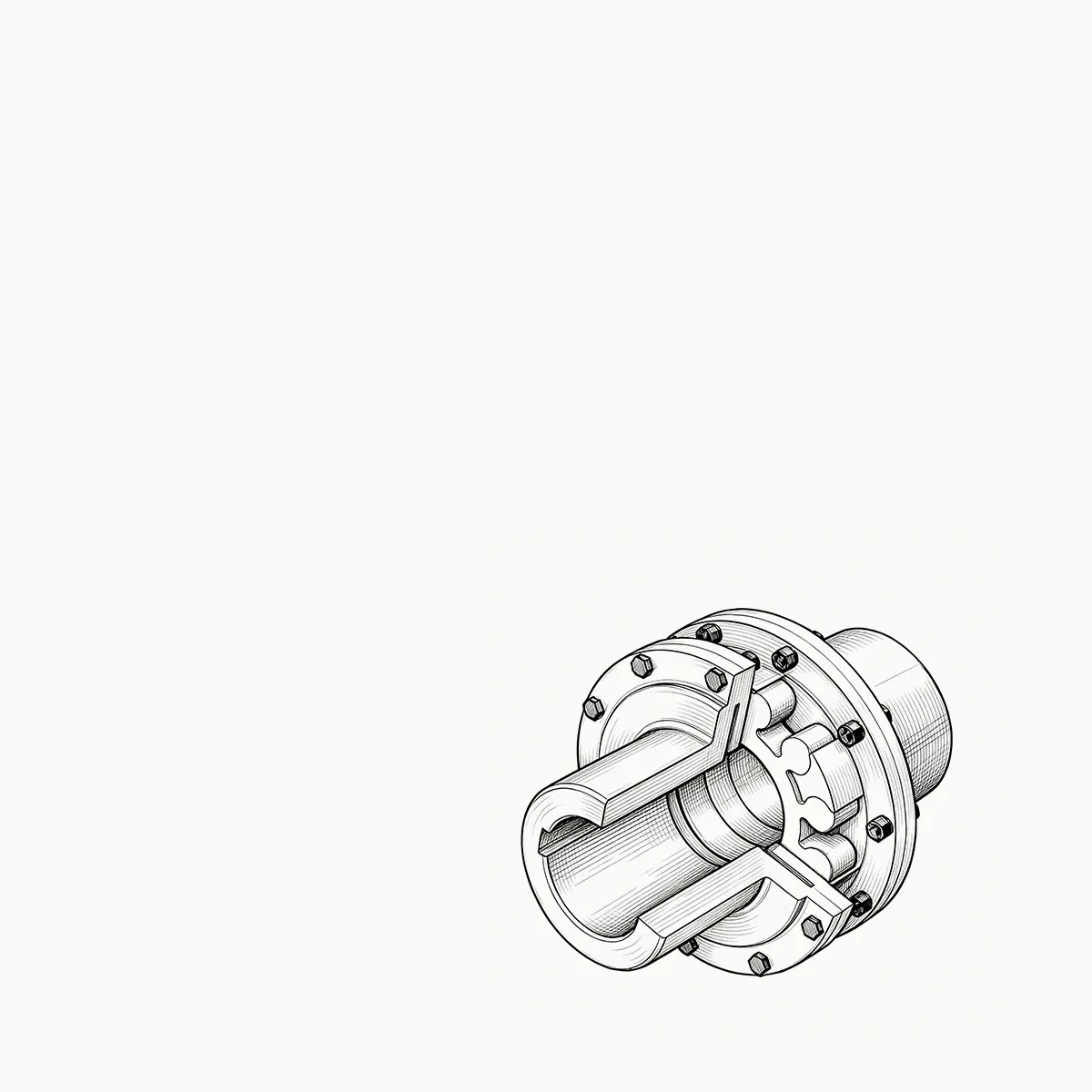
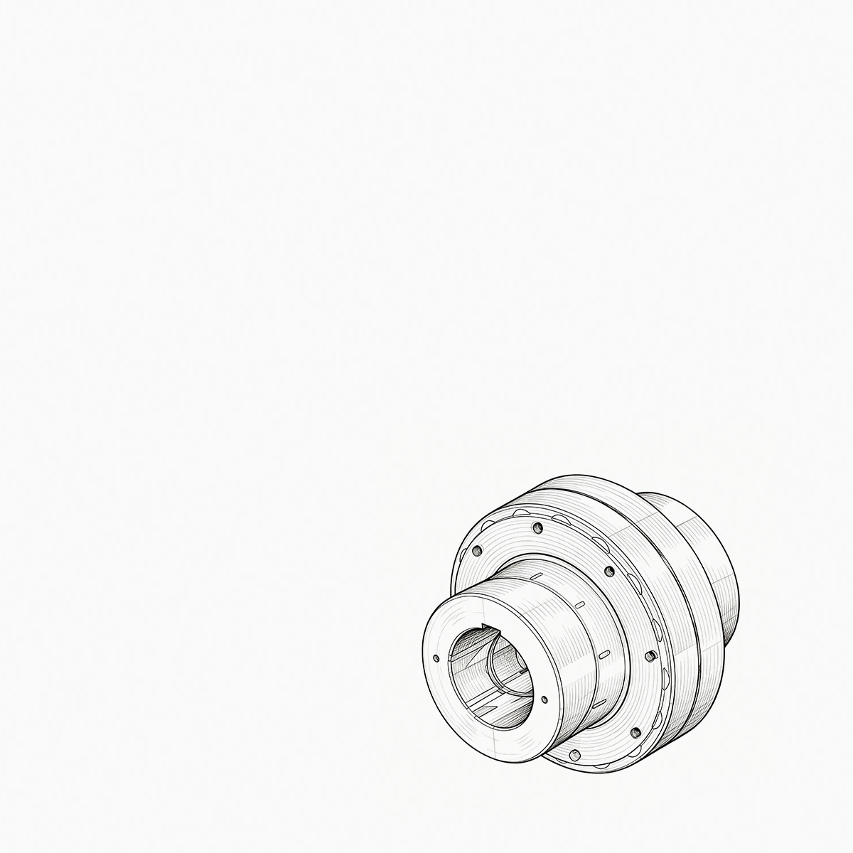
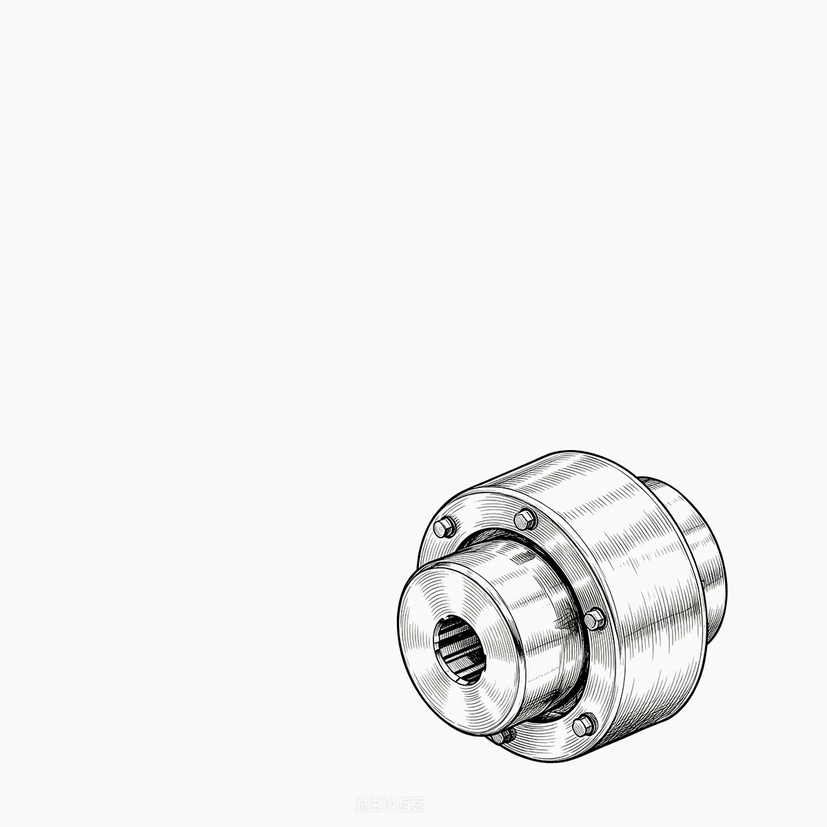
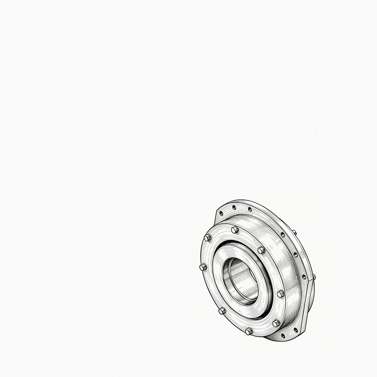

Two quotes land for the same replacement gear coupling: $1,850 from one shop and $2,600 from another. Both promise stan...
READ MORE
WGC Type Vertical Crowned-Gear Coupling: Reliable Power Transmission for Vertical Drive Systems
Admin 2026-10-01Content
- 1 1. The Role of a Coupling in Vertical Transmission Systems
- 2 2. Product Overview
- 3 3. Crowned Gear Tooth Design and Its Operating Principle
- 4 4. Advantages Over Conventional Straight-Tooth Couplings
- 5 5. Lubrication and Sealing for Vertical Installation
- 6 6. Torque Transmission and Load-Carrying Capacity
- 7 7. Compact Construction for Space-Constrained Equipment
- 8 8. Application Areas
- 9 9. Manufacturing Strengths and Engineering Capability
- 10 10. Installation Guidelines
- 11 11. Maintenance and Service Life
- 12 12. Selection Considerations
- 13 13. Why Choose a Specialized Manufacturer
- 14 14. Comparison with Other Flexible Coupling Types
- 15 15. Reliability, Efficiency, and Lifecycle Value
- 16 16. Frequently Asked Questions
- 16.1 16.1 What is a WGC type vertical crowned-gear coupling?
- 16.2 16.2 What makes the coupling suitable for vertical installation?
- 16.3 16.3 What is the purpose of crowned external teeth?
- 16.4 16.4 Can the coupling correct poor initial alignment?
- 16.5 16.5 Is the WGC coupling suitable for crane and hoisting equipment?
- 16.6 16.6 What maintenance does the coupling require?
- 16.7 16.7 What lubricant should be used?
- 16.8 16.8 How does the coupling compare with an elastomeric coupling?
- 16.9 16.9 Can the product be customized?
- 16.10 16.10 What information should be provided when requesting a quotation?
- 17 17. Conclusion
- 18 References
- 19 Product: WGC Type Vertical Crowned-Gear Coupling
Vertical drive systems place special demands on mechanical power transmission components. Unlike horizontal shaft arrangements, vertical installations are strongly affected by gravity, restricted maintenance access, uneven lubricant distribution, axial loading, and limited installation space. A coupling used in this environment must do more than connect two shafts. It must transmit torque efficiently, accommodate shaft misalignment, retain lubricant, resist wear, simplify installation, and maintain dependable operation under changing loads.
The WGC type vertical crowned-gear coupling is designed specifically for these requirements. It is a flexible gear coupling intended for vertical shaft transmission between electric motors, gear reducers, lifting mechanisms, hoisting equipment, metallurgical machinery, mining systems, and other vertically arranged drive units. Its crowned external teeth, integrated sealing arrangement, compact structure, and optimized internal clearance enable it to perform reliably where conventional straight-tooth couplings or general-purpose flexible couplings may experience reduced service life.
By combining a high-capacity gear transmission with flexible misalignment compensation, the WGC coupling provides an effective solution for medium- and high-torque vertical applications. Its structure is developed around the real operating conditions of vertical equipment, including the need to prevent grease migration, control tooth contact, distribute loads evenly, and support efficient assembly in space-constrained machinery.
1. The Role of a Coupling in Vertical Transmission Systems
A coupling connects a driving shaft to a driven shaft while allowing torque to pass from one machine to another. In an ideal system, the two shafts would remain perfectly aligned during operation. In practical equipment, however, alignment changes because of manufacturing tolerances, foundation settlement, thermal expansion, bearing clearance, shaft deflection, installation errors, and variable operating loads.
Vertical systems can be especially challenging because the shafts are arranged along a vertical axis and may be connected to suspended, lifted, or elevated machinery. The coupling may be exposed to axial forces generated by the weight of connected components. Radial loads may change as the driven equipment moves or as the shaft deflects. Angular misalignment can arise from assembly tolerances or deformation of the supporting structure.
If a coupling cannot accommodate these conditions, the resulting problems may include gear tooth edge loading, excessive vibration, accelerated bearing wear, shaft stress, lubricant leakage, overheating, and unplanned downtime. The coupling therefore acts as an important protection and transmission element. It must be flexible enough to compensate for misalignment while remaining rigid enough to transfer torque without excessive torsional movement.
The WGC type coupling addresses these requirements through a gear-based flexible connection. The gear teeth transmit torque through a large contact area, while the crowned tooth profile permits controlled movement between the coupling halves. This combination allows the coupling to maintain power transmission even when the connected shafts are not perfectly collinear.
2. Product Overview
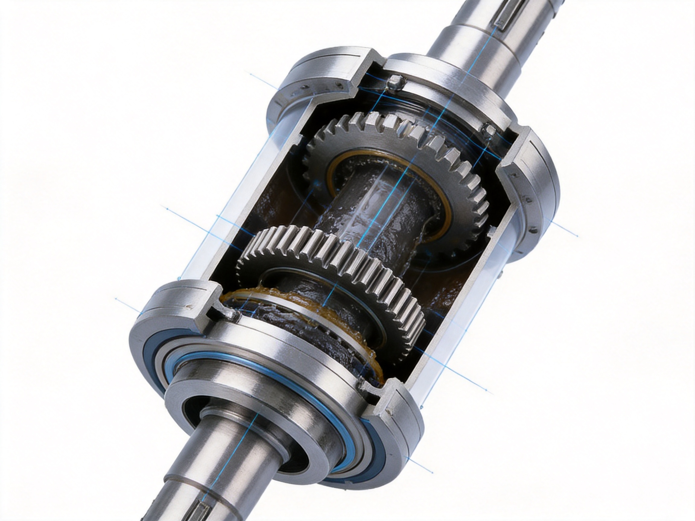
The WGC type vertical crowned-gear coupling is a flexible coupling for vertical shaft applications. Its main construction combines an internal gear sleeve, crowned external gear teeth, sealing end covers, and connected hubs or shaft elements. The coupling is arranged to support vertical installation while preserving the operating principles of a crowned-tooth gear coupling.
The internal gear sleeve engages with the crowned external teeth of the hubs. Torque is transmitted through the meshing teeth, and the spherical tooth geometry allows the hubs to tilt or move within the designed operating range. An optimized backlash value provides sufficient freedom for misalignment compensation without creating excessive impact during reversing, starting, stopping, or fluctuating loads.
The integrated design of the internal gear sleeve and sealing end cover is particularly important in vertical arrangements. Gravity can encourage grease to migrate toward the lower part of the assembly and may increase the risk of leakage if the sealing system is not properly designed. By incorporating the sealing structure into the coupling arrangement, the WGC type improves lubricant retention and supports continuous tooth lubrication.
The coupling is suitable for connecting motors to reducers, reducers to lifting mechanisms, and drive shafts to vertically arranged working machines. It can also be considered for heavy industrial systems in which torque capacity, compact dimensions, and misalignment compensation are more important than the extremely low mass associated with some lightweight coupling types.
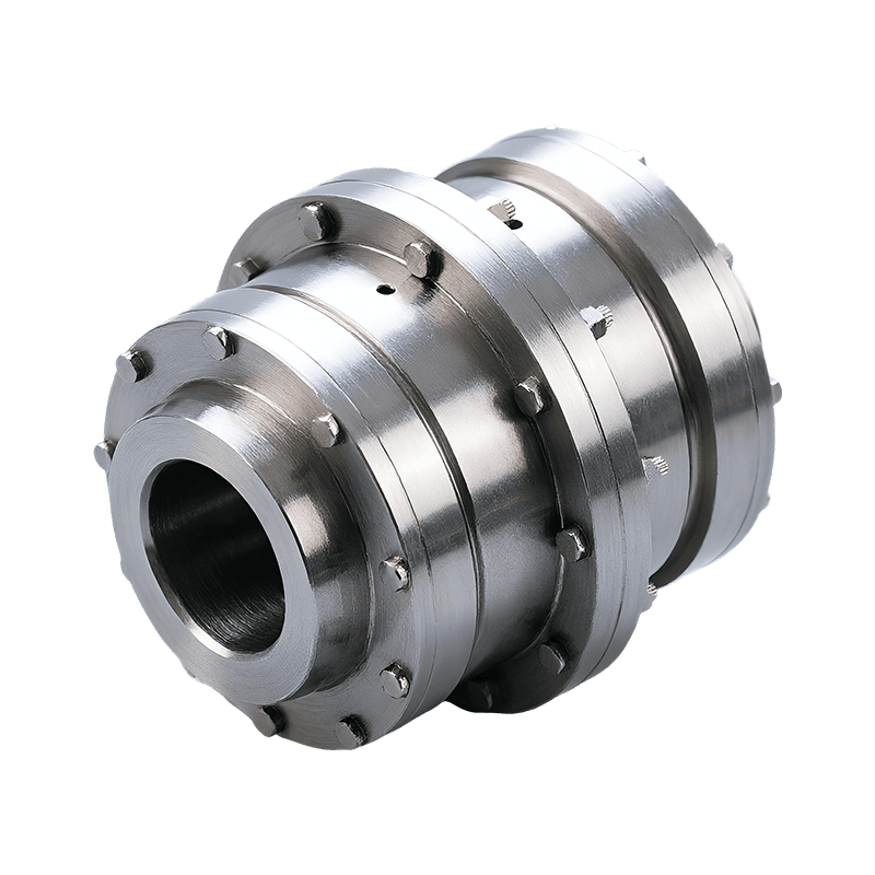
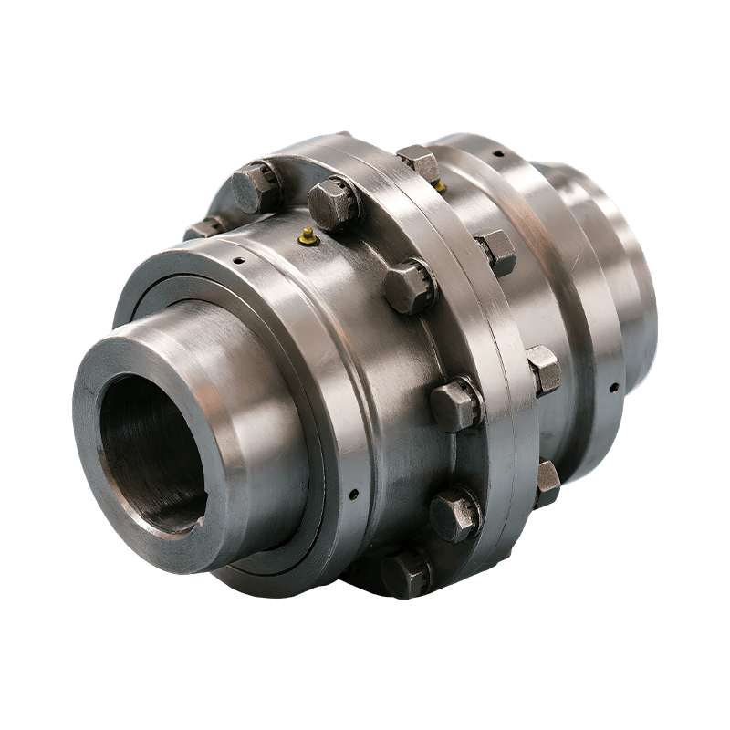
WGC Type Vertical Crowned-Gear Coupling
3. Crowned Gear Tooth Design and Its Operating Principle
The most important performance feature of the WGC coupling is its crowned external tooth profile. A crowned tooth does not have a simple straight flank extending uniformly across the tooth width. Instead, the tooth surface is formed with a controlled spherical or barrel-shaped curvature. The curvature center coincides with the gear axis, allowing the tooth surfaces to remain engaged as the connected shafts move through an angular offset.
When two shafts are perfectly aligned, the load is distributed across a broad portion of the meshing tooth surfaces. When angular misalignment occurs, a conventional straight-tooth gear coupling may make contact near the tooth edges. This concentrates the load into a small area and increases local contact stress. Continued operation under this condition can cause pitting, scuffing, tooth deformation, or premature breakage.
With crowned teeth, the contact position changes more gradually as the shaft angle changes. The spherical profile helps prevent sharp edge contact and maintains a more favorable load path. The result is improved contact behavior, lower localized stress concentration, and greater tolerance of angular displacement.
The crowned tooth profile also supports radial compensation. As the shaft centers move relative to each other, the tooth engagement can accommodate the change without immediately forcing the connected shafts into a rigid alignment. Axial movement may also be accepted within the designed limits, depending on the specific assembly configuration and operating conditions.
It is important to understand that a flexible gear coupling is not intended to compensate for unlimited misalignment. Every application must remain within the allowable angular, radial, and axial displacement specified for the selected size. Nevertheless, the crowned design provides substantially better compensation capability than a simple straight-tooth arrangement when the equipment experiences normal operating movement.
3.1 Angular Misalignment Compensation
Angular misalignment occurs when the two shaft centerlines intersect at an angle rather than remaining parallel. In vertical machinery, it can result from imperfect installation, shaft bending, bearing movement, or deformation of the motor and reducer supports.
The crowned external teeth allow the coupling hubs to operate at an angle while maintaining tooth engagement. Because the tooth surface is curved, contact does not move abruptly to a sharp tooth edge. This helps maintain a stable torque path and reduces the possibility of severe edge loading.
3.2 Radial Misalignment Compensation
Radial misalignment occurs when the two shaft centerlines are parallel but offset. Thermal growth, foundation movement, bearing clearance, and assembly tolerances can all produce radial displacement. The flexible gear engagement allows controlled relative movement between the two shafts.
By accepting radial displacement, the coupling reduces the need for connected components to absorb alignment errors. This can help reduce additional loads on motor bearings, reducer bearings, and driven-machine supports.
3.3 Axial Movement
Vertical installations may generate axial movement due to the weight of suspended components, thermal expansion, thrust forces, or movement within the connected machinery. The coupling’s internal clearance and structural arrangement can permit limited axial displacement while maintaining torque transmission.
Axial movement must be evaluated together with the thrust capacity of the connected shafts and bearings. The coupling should not be used as a substitute for a thrust bearing or an axial positioning device. Correct system design requires the coupling, bearings, shafts, and supporting structure to share loads according to their intended functions.
4. Advantages Over Conventional Straight-Tooth Couplings
The WGC type coupling offers several technical advantages compared with conventional straight-tooth gear couplings. The differences are most noticeable in systems exposed to angular misalignment, fluctuating loads, limited installation space, and demanding duty cycles.
| Performance Feature | WGC Type Vertical Crowned-Gear Coupling | Conventional Straight-Tooth Coupling | Practical Benefit |
|---|---|---|---|
| Tooth geometry | Crowned external teeth with spherical curvature | Predominantly straight tooth flanks | More stable contact during angular displacement |
| Angular misalignment | Designed to accommodate controlled angular movement | More likely to develop edge contact | Reduced localized stress and tooth wear |
| Load distribution | Improved contact distribution across the working tooth area | Load may concentrate toward tooth edges | Improved durability under changing alignment |
| Vertical lubrication | Integrated sleeve and sealing end-cover arrangement | May require less specialized sealing provisions | Better grease retention in vertical layouts |
| Torque density | High torque capacity within a compact envelope | Varies by design and size | Efficient use of installation space |
| Application range | Vertical motors, reducers, hoists, and heavy machinery | General shaft connection applications | Better adaptation to vertical industrial equipment |
The crowned profile does not merely increase flexibility. It changes the way the teeth carry load. By reducing the probability of sharp edge contact, the coupling can operate more smoothly under real-world alignment conditions. This is especially valuable in equipment that cannot be perfectly aligned during every stage of operation.
Another advantage is the relationship between torque capacity and outside diameter. For the same general envelope, a gear coupling can transmit more torque than many elastomeric or pin-based flexible coupling designs. The WGC type is therefore appropriate when high power must be transmitted through a relatively compact vertical arrangement.
5. Lubrication and Sealing for Vertical Installation
Lubrication is one of the most important design considerations for a crowned-gear coupling. The meshing gear teeth operate under high contact pressure, and an adequate grease film is necessary to minimize friction, wear, and heat generation. If grease escapes or is unevenly distributed, the teeth may operate under boundary lubrication or dry contact conditions.
Vertical mounting creates additional challenges. Gravity can cause lubricant to move downward, particularly when the coupling experiences temperature changes or vibration. Poorly controlled leakage can reduce the amount of grease at the active tooth surfaces. It can also contaminate adjacent components, create housekeeping problems, and require more frequent maintenance.
The WGC design combines the internal gear sleeve and sealing end cover into an integrated arrangement. This helps create a more controlled lubrication chamber around the gear teeth. The sealing structure is intended to retain grease within the coupling and reduce the risk of leakage associated with vertical orientation.
Continuous lubrication has several benefits. It reduces tooth friction, limits surface temperature, protects against corrosion, and helps preserve the designed tooth profile. It also contributes to quieter operation because a properly lubricated gear mesh produces less sliding resistance and fewer impact effects.
Lubricant selection remains important. The grease should be compatible with the operating temperature, speed, contact pressure, sealing materials, and environmental conditions. In dusty, wet, corrosive, or high-temperature environments, the maintenance schedule and grease specification should be established before commissioning.
5.1 Lubrication Practices
Before installation, the coupling should be inspected to confirm that the tooth surfaces, sealing components, and internal chamber are clean. The recommended lubricant should be applied in the correct amount. Excess grease can increase churning losses and internal pressure, while insufficient grease may result in rapid tooth wear.
During operation, inspection should focus on leakage, abnormal temperature, unusual noise, vibration, and changes in coupling movement. Grease leakage does not always indicate immediate failure, but it should never be ignored. A leaking seal can eventually reduce the available lubricant and allow dust or moisture to enter the gear chamber.
For equipment with a high duty cycle, frequent starts and stops, reversing operation, shock loading, or high ambient temperature, lubrication intervals may need to be shorter. Maintenance personnel should follow the equipment manufacturer’s recommendations and adjust the schedule based on actual service conditions.
6. Torque Transmission and Load-Carrying Capacity
Gear couplings transmit torque through multiple engaged teeth rather than through a single flexible element. This allows the coupling to transfer substantial power while maintaining a relatively compact structure. The WGC type is therefore well suited to medium- and high-torque applications such as hoisting machinery, metallurgical equipment, mining systems, and large vertical drive units.
The crowned tooth design improves the load path when misalignment is present. In a rigidly aligned condition, the tooth surfaces can share the transmitted load effectively. If the shafts move slightly during operation, the curved profile helps prevent the load from becoming concentrated at one edge. This provides a more stable operating condition than a straight-tooth design under comparable displacement.
Torque capacity depends on more than the coupling nominal size. The actual selection must consider motor power, operating speed, service factor, starting torque, braking torque, shock loading, reversing frequency, duty cycle, ambient temperature, shaft dimensions, and allowable misalignment. A coupling that is adequate for steady continuous rotation may be undersized for a crane hoist with repeated starts, stops, and lifted loads.
Service factors are especially important in lifting and mining applications. Dynamic loads may be considerably higher than the average operating torque. The coupling should be selected using the peak or equivalent design torque rather than motor rated torque alone. In systems with frequent impact or abrupt braking, the designer should also evaluate torsional vibration and transient loads.
6.1 Stable Torque Transfer
A stable load-transfer path helps reduce torsional shock between the motor and driven machine. The coupling’s gear teeth maintain positive engagement, while the flexible tooth geometry accommodates alignment changes. This combination supports smooth power transmission without requiring the coupling to be completely rigid.
Stable torque transfer is beneficial for motors, reducers, shafts, bearings, and gearboxes. It can reduce the possibility that an alignment movement will be converted into an excessive radial or angular force. It also helps maintain consistent operation when the driven load changes during lifting, conveying, crushing, rolling, or other industrial processes.
7. Compact Construction for Space-Constrained Equipment
Vertical machinery often has limited access around the shaft line. Motor and reducer assemblies may be positioned inside frames, towers, hoisting structures, or enclosed drive compartments. A coupling with an unnecessarily large outer diameter or complicated installation sequence can increase the size and cost of the entire machine.
The WGC type coupling has a compact overall configuration and a clear assembly arrangement. Its gear sleeve and sealing components are organized to fit within a practical envelope while retaining the capacity required for industrial power transmission. This can help equipment designers reduce the required installation space and simplify the layout of guards and support structures.
A compact coupling may also reduce the overhung mass on connected shafts. Lower mass can benefit bearing loading and dynamic response, although the complete assembly must always be evaluated rather than the coupling alone. The coupling guard should provide adequate clearance for normal movement and should not interfere with the sealing end cover or inspection points.
Clear assembly arrangements are particularly valuable during maintenance. When the coupling halves, sleeve, seals, and fasteners are logically arranged, technicians can inspect or replace components with less disassembly of adjacent equipment. This can reduce maintenance time and lower the risk of incorrect reassembly.
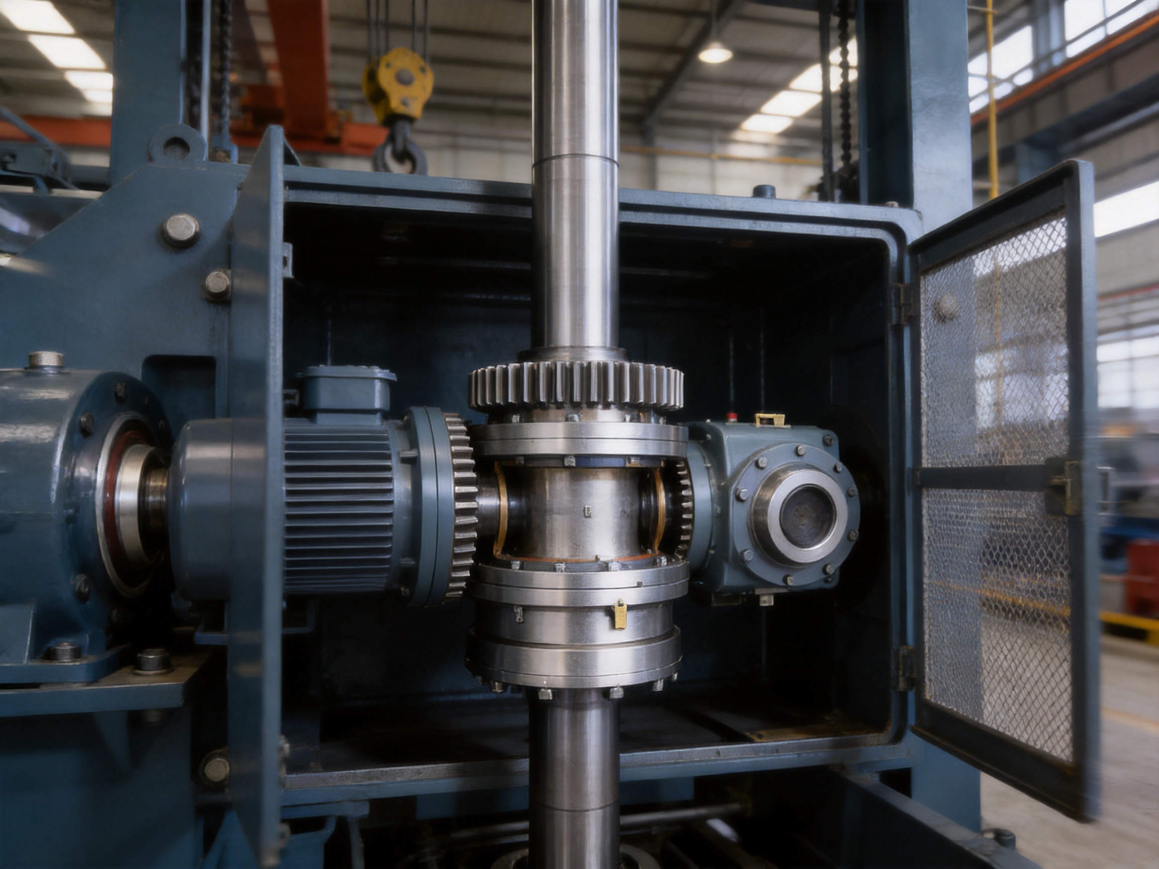
8. Application Areas
8.1 Hoisting and Crane Equipment
Crane and hoisting equipment frequently operates under variable loads and repeated acceleration and deceleration. Vertical lifting systems can generate dynamic torque, sudden load changes, and shaft movement. A coupling must transmit torque reliably while accommodating reasonable alignment changes between the motor, reducer, and drum or lifting mechanism.
The WGC type coupling is suitable for vertical crane drive arrangements where compact dimensions, high torque capacity, and dependable lubrication are required. Its crowned gear teeth help manage angular displacement, while the integrated sealing design is beneficial where the coupling is installed vertically within a hoist assembly.
8.2 Metallurgical Machinery
Metallurgical equipment often operates in environments with high temperature, dust, vibration, and demanding production cycles. Vertical drives may be found in rolling, conveying, processing, lifting, and furnace-related machinery. Equipment reliability is essential because an unexpected coupling failure can interrupt an entire production line.
For these applications, the coupling must be manufactured accurately and protected against lubricant loss and contamination. The WGC type provides a heavy-duty gear transmission and a design intended for stable lubrication. Correct material selection, heat treatment, sealing, and maintenance remain necessary for long-term performance in severe plant conditions.
8.3 Mining Equipment
Mining machinery is exposed to dust, shock loads, vibration, and difficult maintenance conditions. Vertical drive systems may be used in hoists, crushers, feeders, elevators, conveyors, and material-handling equipment. In such environments, a coupling must be robust and tolerant of operating variation.
The high torque density of a gear coupling is useful where powerful motors and reducers must be connected within a restricted space. The crowned tooth profile can help accommodate alignment changes caused by structural movement or bearing displacement. Sealing and lubrication are especially important because abrasive particles can accelerate gear tooth wear if they enter the coupling chamber.
8.4 Large Vertical Machinery
Large vertical machines may have long shaft lines, heavy rotating assemblies, or support structures that change shape under load. Such systems require careful control of radial, angular, and axial displacement. The WGC coupling can provide a flexible connection between major drive components while preserving a high-capacity torque path.
Engineering evaluation should include shaft critical speeds, bearing stiffness, structural movement, torsional vibration, and the complete load spectrum. The coupling is one part of the drive system, and its performance depends on correct integration with the surrounding machinery.
8.5 General Industrial Drive Units
In addition to specialized heavy equipment, the coupling may be used in industrial drive units where a vertical motor is connected to a reducer, pump, agitator, conveyor, or other driven machine. It is appropriate when the application requires more torque capacity and misalignment tolerance than a simple elastomeric coupling can provide.
9. Manufacturing Strengths and Engineering Capability
The performance of a crowned-gear coupling depends not only on its basic design but also on manufacturing accuracy. Tooth geometry, concentricity, surface finish, heat treatment, sealing fit, and assembly quality all influence service life. A coupling with the correct theoretical profile may still perform poorly if production controls are inadequate.
Zhenjiang Orienthold Machinery Co., Ltd. is a medium-sized enterprise specializing in couplings and papermaking machinery. Its capabilities integrate product design, production, quality supervision, inspection, testing, and service. This integrated structure supports the development of couplings for transportation, metallurgy, chemical engineering, mining, construction, hoisting, and other industrial sectors.
The company’s production approach is based on combining technical design with practical manufacturing experience. This is important for vertical crowned-gear couplings because the product must satisfy several requirements at the same time: accurate gear geometry, reliable sealing, sufficient mechanical strength, appropriate flexibility, and convenient assembly.
9.1 Engineering and Product Design
Product design begins with the intended transmission conditions. Engineers must consider torque, speed, shaft diameter, misalignment, installation direction, environmental conditions, lubrication, and maintenance access. For a vertical coupling, gravity and sealing are not secondary details; they are part of the primary design problem.
Design work may include analysis of tooth contact, load distribution, shaft movement, component stress, and assembly clearances. The crowned profile must be formed accurately so that it provides flexibility without reducing effective tooth engagement. Internal clearances must be controlled to prevent unwanted impact while allowing the required misalignment.
Customization capability is also valuable. Different customers may require special shaft bores, keyways, flange dimensions, mounting arrangements, corrosion protection, or material specifications. A manufacturer that can coordinate design and production is better positioned to provide a coupling suited to the actual machine rather than a generic component that only partially matches the application.
9.2 Precision Machining
Precision machining is essential for the internal gear sleeve and external crowned teeth. The machining process must control tooth dimensions, pitch accuracy, concentricity, runout, surface finish, and the relationship between the tooth profile and the shaft bore. These factors influence how the coupling carries load and how smoothly it operates.
Advanced production equipment supports repeatable machining and helps maintain consistency among coupling components. Proper process planning also reduces the possibility of dimensional variation that could cause uneven tooth contact or difficulty during assembly.
Machined surfaces that interact with seals require particular attention. Surface irregularities, excessive runout, or incorrect fits can increase leakage and shorten seal life. The sealing end cover and sleeve must be produced and assembled with suitable dimensional control.
9.3 Heat Treatment and Material Performance
Gear teeth are exposed to repeated contact and sliding stresses. Material selection and heat treatment therefore play a major role in wear resistance, tooth strength, and fatigue performance. The appropriate treatment depends on the coupling size, torque level, operating speed, environmental conditions, and production requirements.
Controlled heat treatment can improve surface hardness while preserving sufficient core toughness. This balance helps the tooth surfaces resist pitting and wear without becoming excessively brittle. Heat treatment quality should be verified through appropriate inspection and process records.
Other components, including sleeves, hubs, fasteners, and sealing supports, must also be selected for the required strength and service environment. A coupling is a system of interacting parts, and the weakest component can determine overall reliability.
9.4 Inspection and Testing
A comprehensive inspection system helps ensure that finished couplings conform to design requirements. Typical quality checks may include dimensional inspection, tooth profile verification, bore and keyway measurement, concentricity inspection, surface condition checks, hardness testing, and visual examination of seals and machined surfaces.
Functional or assembly checks can confirm that the coupling halves fit correctly, that the sleeve moves as intended, and that the sealing components are properly positioned. Depending on the product size and application, additional tests may be conducted to verify balance, runout, or load-related performance.
Orienthold Machinery operates with complete inspection and testing equipment and a strict quality supervision system. Its products comply with applicable national standards, while its broader machinery production technology and quality are developed to serve international customers. This quality-oriented approach is important for industrial buyers who require consistent replacement parts and dependable performance across multiple machines.
10. Installation Guidelines
Correct installation is essential to obtain the intended performance of a vertical crowned-gear coupling. Even a precisely manufactured coupling can suffer early wear if the shafts are poorly aligned, the lubricant is incorrect, or the sealing components are damaged during assembly.
10.1 Shaft and Bore Preparation
Before installation, the shaft ends should be checked for correct diameter, keyway dimensions, surface condition, and burrs. Shaft surfaces must be clean and free from oil, dirt, rust, and raised metal that could prevent the hub from seating properly. The key should fit correctly and should not create excessive interference or looseness.
The shaft centerlines should be measured and adjusted as accurately as practical before the coupling is installed. The coupling can compensate for operating misalignment, but it should not be used to correct careless installation. Initial alignment should be significantly better than the maximum allowable operating displacement.
10.2 Assembly of the Coupling Halves
The hubs should be installed according to the specified axial positions and insertion dimensions. The internal gear sleeve and sealing end cover should be handled carefully to avoid damaging tooth surfaces or seals. Any protective packaging, temporary coating, or foreign material should be removed from the working surfaces before final assembly.
Fasteners should be tightened using suitable tools and the recommended sequence. If the design requires specific tightening torque, the values should be followed carefully. Incorrect fastener tightening may lead to looseness, distortion, or damage to the sleeve and end cover.
10.3 Lubricant Filling
Grease should be added according to the product instructions. The coupling should not be overfilled, because excessive grease may cause heat buildup and pressure at the seals. At the same time, the tooth surfaces must receive sufficient coverage for the expected operating conditions.
After installation, the sealing area should be inspected for correct seating. The first operating period should include a careful check for abnormal noise, vibration, temperature rise, or grease leakage.
11. Maintenance and Service Life
Regular maintenance helps preserve the performance of the WGC type coupling. Maintenance requirements depend on operating speed, torque, duty cycle, environment, and the consequences of downtime. Heavy industrial equipment should generally receive a documented coupling inspection program.
Visual inspection should look for grease leakage, damaged seals, loose fasteners, corrosion, abnormal movement, and evidence of contact between the coupling and its guard. Unusual noise may indicate tooth wear, insufficient lubrication, excessive backlash, or misalignment. Vibration trends can provide early information about changes in shaft alignment or coupling condition.
When the coupling is opened for inspection, the gear teeth should be checked for pitting, scoring, cracking, plastic deformation, and unusual wear patterns. Edge wear may indicate excessive angular misalignment. Wear concentrated on one side may suggest radial offset or incorrect assembly. Discoloration may indicate overheating or insufficient lubrication.
Seals should be replaced if they become hardened, cracked, torn, or permanently deformed. Reusing damaged seals can allow grease to escape and contaminants to enter. Tooth surfaces should be cleaned with suitable materials, and abrasive tools should not be used in a way that changes the designed profile.
Maintenance records should include inspection dates, operating hours, lubricant additions, seal replacements, alignment measurements, and observed wear. Such records help identify trends and support preventive maintenance planning.
12. Selection Considerations
Selecting the correct WGC coupling size requires a complete understanding of the connected drive. The following factors should be evaluated before final selection:
Rated motor power and operating speed establish the basic transmitted torque. The designer should also consider starting torque, braking torque, acceleration time, reversing frequency, and any known overload conditions.
The driven equipment determines the service factor. A smooth, continuous process generally produces less severe loading than a hoist, crusher, rolling machine, or reciprocating mechanism. Applications with frequent impact require additional capacity and careful torsional evaluation.
Shaft diameter and available length determine the hub bore and mounting arrangement. Keyways, splines, shrink fits, or other connection methods should be specified clearly. The coupling must fit the shaft without compromising hub strength.
Alignment conditions should be measured or estimated realistically. Angular, radial, and axial movement must remain within the allowable values for the selected coupling. The designer should account for changes that occur during operation rather than relying only on cold static alignment.
Environmental conditions include temperature, dust, moisture, corrosive chemicals, washdown procedures, altitude, and installation location. These factors influence material selection, sealing, lubricant choice, and maintenance intervals.
Available space and installation access should be reviewed before ordering. The coupling must fit within the machine envelope, and sufficient room must remain for assembly, inspection, removal, and guard installation.
| Selection Item | Information to Confirm | Why It Matters |
|---|---|---|
| Power and speed | Motor rating, operating rpm, starting and braking conditions | Determines transmitted and transient torque |
| Driven machine | Hoist, reducer, conveyor, crusher, pump, or other equipment | Establishes service factor and load severity |
| Shaft details | Diameter, length, keyway, spline, bore, and fit | Ensures safe and accurate mechanical connection |
| Misalignment | Angular, radial, and axial movement | Confirms that coupling flexibility is adequate |
| Environment | Temperature, dust, moisture, chemicals, and washdown | Guides seal, grease, material, and maintenance selection |
| Installation position | Vertical direction, access, guard, and surrounding clearance | Supports correct assembly and serviceability |
13. Why Choose a Specialized Manufacturer
Industrial coupling procurement is not limited to comparing catalog dimensions. A specialized manufacturer can help evaluate application loads, shaft arrangements, installation conditions, and customization requirements. This support is valuable when a coupling is installed in critical equipment or when the operating conditions are outside standard service assumptions.
Orienthold Machinery combines coupling production with design and service capabilities. This allows customers to request technical consultation before purchase, discuss customized dimensions, and coordinate logistics and maintenance support. A one-stop approach can simplify communication between the coupling supplier and the equipment manufacturer.
The company serves industries including transportation, metallurgy, chemical engineering, mining, construction, and hoisting. Experience across these sectors provides practical insight into different loading conditions and installation challenges. Its product range also includes several other coupling types, enabling engineers to compare gear, diaphragm, pin, tire, plum, and universal coupling solutions according to application needs.
Quality supervision and complete inspection equipment support consistency during production. For customers managing multiple machines, consistency is important because replacement couplings must match the original installation and deliver predictable performance. Reliable documentation, responsive technical service, flexible logistics, and maintenance assistance further improve the total value of the product.
14. Comparison with Other Flexible Coupling Types
Different coupling designs are suitable for different operating conditions. Elastomeric couplings can provide vibration damping and simple maintenance, but their torque and temperature capabilities may be limited by the elastic element. Diaphragm couplings can offer high-speed, low-backlash performance, but they may be less suitable for applications requiring large misalignment compensation under heavy industrial loads.
Pin couplings can provide useful flexibility and shock absorption, while tire couplings are often selected for damping and relatively simple installation. Universal couplings are appropriate for larger angular movements in specific shaft arrangements. A crowned-gear coupling is generally selected when high torque density, positive mechanical engagement, and broad misalignment compensation are priorities.
The WGC type is particularly appropriate when the coupling must combine compact construction with heavy-duty torque transmission in a vertical orientation. Its primary advantages are not universal substitutes for every coupling type. Instead, they address a defined group of requirements: vertical installation, gear-tooth load transmission, angular compensation, high torque capacity, and lubricant retention.
15. Reliability, Efficiency, and Lifecycle Value
Transmission efficiency is influenced by gear contact, lubrication, alignment, sealing friction, and operating speed. A properly selected and lubricated WGC coupling provides an efficient mechanical connection with relatively low power loss compared with systems that use excessive sliding or deformation in the flexible element.
Lifecycle value includes more than initial purchase price. A coupling that lasts longer, requires fewer unplanned shutdowns, and protects connected equipment can reduce the total cost of ownership. Improved tooth contact may reduce wear, while effective sealing may extend lubricant service intervals and protect internal components from contamination.
Compact construction can also reduce the size of associated guards, frames, and supports. Easier access and clear assembly may lower labor costs during installation and replacement. When these benefits are combined with technical support and customization, the total value of the coupling can be greater than the price of the component alone.
Reliability ultimately depends on the complete system. Correct selection, precision manufacturing, proper alignment, suitable lubrication, effective guarding, regular inspection, and timely replacement of worn parts are all necessary. The WGC design provides a strong foundation, but good engineering and maintenance practices are essential to realize its full potential.
16. Frequently Asked Questions
16.1 What is a WGC type vertical crowned-gear coupling?
It is a flexible gear coupling designed for vertical shaft transmission. It connects components such as motors, reducers, lifting mechanisms, and vertically arranged drive units while transmitting torque and accommodating controlled angular, radial, and axial misalignment.
16.2 What makes the coupling suitable for vertical installation?
Its structure is developed with vertical operating conditions in mind. The integrated internal gear sleeve and sealing end-cover arrangement improves grease retention and reduces the risk of lubricant leakage caused by gravity. The compact layout also supports installation in restricted vertical spaces.
16.3 What is the purpose of crowned external teeth?
Crowned teeth have a curved spherical profile that helps maintain favorable contact when the connected shafts are angularly displaced. They reduce the likelihood of sharp edge contact, distribute loads more evenly, and improve the coupling’s ability to compensate for misalignment.
16.4 Can the coupling correct poor initial alignment?
No. The coupling is designed to accommodate operating misalignment within specified limits, not to replace proper installation. The shafts should be aligned as accurately as possible before commissioning to prevent unnecessary tooth loads, vibration, and wear.
16.5 Is the WGC coupling suitable for crane and hoisting equipment?
Yes. Its high torque capacity, compact structure, and flexible gear engagement make it suitable for many crane and hoisting applications. The selection must account for starting torque, braking torque, shock loads, lifting frequency, and the required service factor.
16.6 What maintenance does the coupling require?
Maintenance generally includes checking lubricant condition and quantity, inspecting seals, monitoring leakage, examining gear teeth for wear, checking fasteners, and measuring abnormal noise or vibration. The exact interval depends on operating conditions and the equipment manufacturer’s recommendations.
16.7 What lubricant should be used?
The lubricant should be selected according to the coupling instructions and the actual temperature, speed, load, and environmental conditions. A compatible industrial gear-coupling grease should be used, and incompatible greases should not be mixed without technical confirmation.
16.8 How does the coupling compare with an elastomeric coupling?
The WGC coupling generally offers higher torque density and greater resistance to heavy industrial loading. An elastomeric coupling may provide stronger vibration damping and simpler maintenance in lighter applications. The appropriate choice depends on torque, speed, misalignment, temperature, damping requirements, and duty cycle.
16.9 Can the product be customized?
Customization may be available for shaft bores, keyways, dimensions, mounting arrangements, materials, sealing provisions, and other application-specific requirements. Customers should provide complete technical information so the manufacturer can confirm feasibility and performance.
16.10 What information should be provided when requesting a quotation?
Useful information includes motor power, operating speed, torque, shaft diameters, shaft spacing, installation direction, expected misalignment, duty cycle, environmental conditions, starting and braking details, and any dimensional limitations. Photographs or drawings of the existing installation can also assist technical evaluation.
17. Conclusion
The WGC type vertical crowned-gear coupling is a specialized solution for demanding vertical power transmission systems. Its crowned external teeth provide improved contact behavior under angular displacement, while the gear construction delivers high torque capacity in a compact envelope. The integrated sleeve and sealing end-cover arrangement supports lubricant retention and addresses a key challenge of vertical installation.
Compared with conventional straight-tooth couplings, the WGC design offers better tolerance of operating misalignment, reduced localized tooth stress, and more stable load distribution. These characteristics make it suitable for electric motor and reducer connections, crane and hoisting systems, metallurgical machinery, mining equipment, and large vertical industrial drives.
Its performance is supported by the manufacturing strengths of Zhenjiang Orienthold Machinery Co., Ltd., including integrated design and production, precision machining, quality supervision, inspection capability, customization support, and service for industrial customers. By combining engineering knowledge with controlled manufacturing processes, the company provides coupling solutions intended for reliable and continuous operation.
For the best results, users should select the coupling according to the complete operating profile, perform accurate initial alignment, use suitable lubricant, protect the sealing system, and establish a regular inspection program. When correctly specified and maintained, the WGC type vertical crowned-gear coupling can provide an efficient, durable, and dependable connection for high-demand vertical drive applications.
References
1. General Principles of Mechanical Power Transmission and Flexible Coupling Design.
2. Industrial Gear Coupling Engineering Practices: Tooth Contact, Misalignment, Lubrication, and Maintenance.
3. Machinery Alignment and Installation Guidelines for Rotating Equipment.
4. Industrial Gear and Coupling Maintenance Procedures.
5. Standards and Technical Practices for Torque Transmission Components.
6. Manufacturer Product Information for WGC Type Vertical Crowned-Gear Couplings.
7. Industrial Machinery Quality Inspection and Testing Practices.
Product: WGC Type Vertical Crowned-Gear Coupling
PREV: LLA Type Tyre Coupling: Flexible, Reliable Power Transmission for Demanding Industrial SystemsNEXT: WGZ Type Crowned-Gear Coupling with Brake Wheel: Integrated Torque Transmission and Reliable Braking for Heavy-Duty Machinery
Be the First to Know
For exclusive deals and latest offers, sign up by entering your email address below.
Related products
News
-
-
China's coupling industry is at a critical historical juncture of transformation from scale expansion to quality and eff...
READ MORE -
Gear Coupling vs. Drum Gear Coupling: The Core Difference The main difference is that "gear coupling" is a broad catego...
READ MORE -
Consider a 250 kW crane hoist that begins to vibrate only when the load is lifted. The drum gear coupling is inspected ...
READ MORE -
A mill drive rarely fails without warning. It knocks at speed, throws a smear of dark grease around the sleeve flange, ...
READ MORE -
Industrial Couplings: The Definitive Technical Encyclopedia – Classification, Sizing, Failure Prevention, and Lifecycle...
READ MORE


ABOUT US
PRODUCTS
INDUSTRIES
CONTACT US
- Phone: +86-18652865511
- Email: sales@ohmach.com
- Address: No.1, Minying Developing Zone, Zhenjiang, Jiangsu, China
Copyright Zhenjiang Orienthold Machinery Co., Ltd. All Rights Reserved.
 Custom Industrial Shaft Coupling Manufacturers