 English
 русский
 Português
 عربى
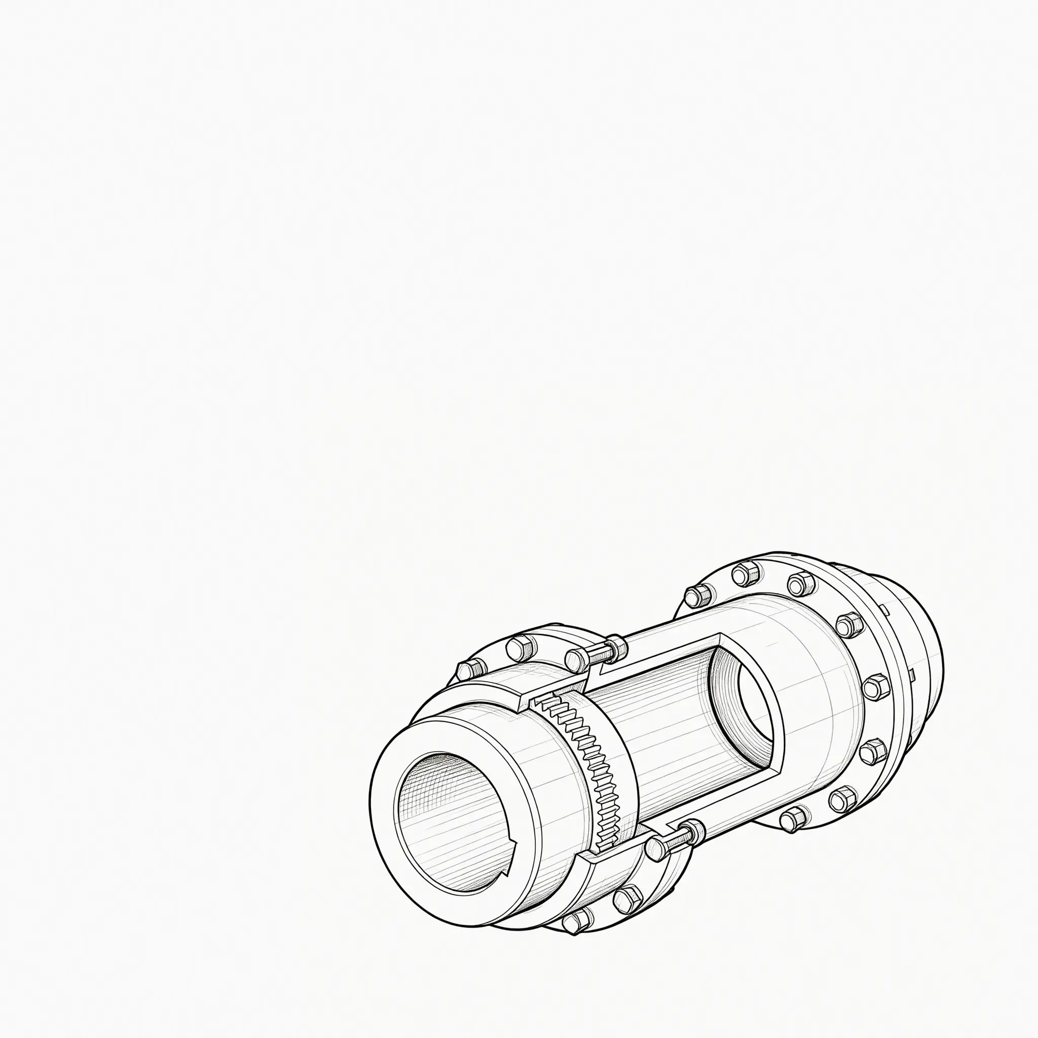
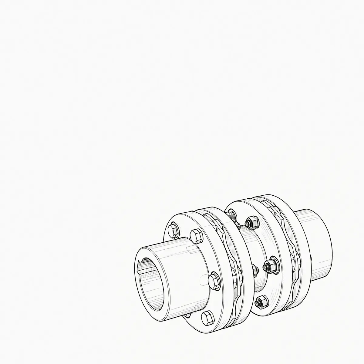
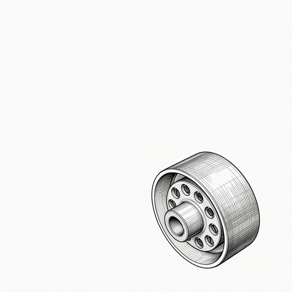
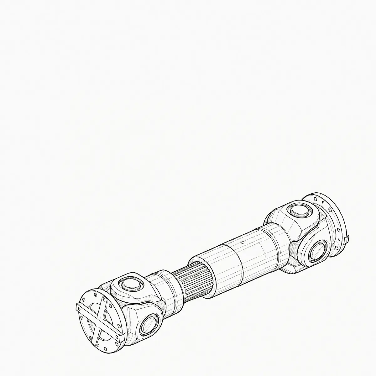
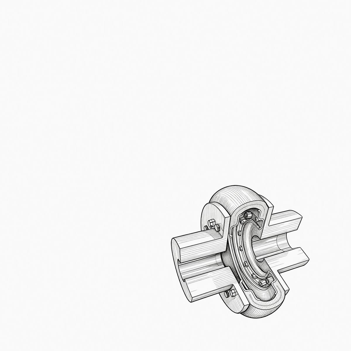

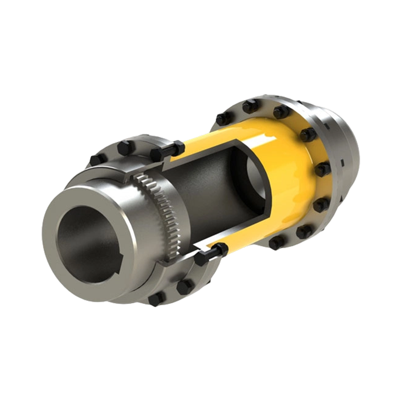
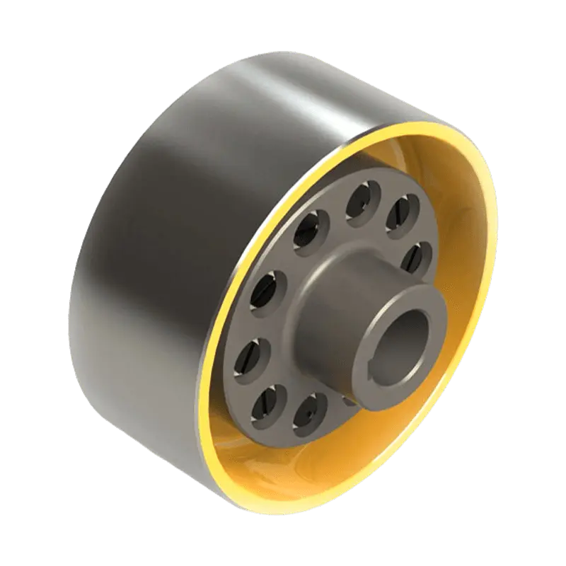
Consider a 250 kW crane hoist that begins to vibrate only when the load is lifted. The drum gear coupling is inspected ...
READ MORE
WGZ Type Crowned-Gear Coupling with Brake Wheel: Integrated Torque Transmission and Reliable Braking for Heavy-Duty Machinery
Admin 2026-09-21Content
- 1 Introduction
- 2 What Is a WGZ Crowned-Gear Coupling?
- 3 Integrated Transmission and Braking Function
- 4 Crowned Tooth Profile and Misalignment Compensation
- 5 Type I and Type II Sealing Configurations
- 6 Performance Advantages in Heavy-Duty Applications
- 7 Comparison with Conventional Coupling Arrangements
- 8 Applications of the WGZ Coupling
- 9 Manufacturing Process and Quality Strengths
- 10 Why Choose an Integrated Manufacturer?
- 11 Selection Guidelines
- 12 Installation and Commissioning
- 13 Maintenance and Service Practices
- 14 Safety Considerations
- 15 Q&A
- 15.1 What is the main function of the WGZ Type Crowned-Gear Coupling with Brake Wheel?
- 15.2 How does the crowned tooth profile improve performance?
- 15.3 Does the coupling eliminate the need for shaft alignment?
- 15.4 What is the difference between Type I and Type II?
- 15.5 Can the WGZ coupling be used with any brake?
- 15.6 Which industries use this type of coupling?
- 15.7 What information is needed for product selection?
- 15.8 Does the coupling require lubrication?
- 15.9 How does the integrated brake drum benefit equipment design?
- 15.10 Can the product be customized?
- 15.11 What quality capabilities support production?
- 15.12 How should the coupling be maintained?
- 16 Conclusion
- 17 References
- 18 Product: WGZ Type Crowned-Gear Coupling with Brake Wheel
Introduction
Heavy-duty machinery depends on dependable power transmission, accurate shaft alignment, and safe stopping performance. In hoisting equipment, mining machinery, metallurgical plants, conveying systems, and other large rotating installations, the coupling is not simply a connector between two shafts. It is a critical mechanical component that transfers torque, accommodates installation and operating misalignment, protects connected equipment, and contributes to overall system safety.
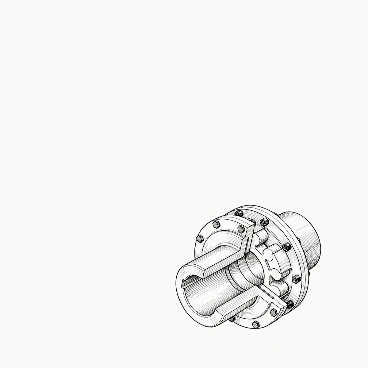
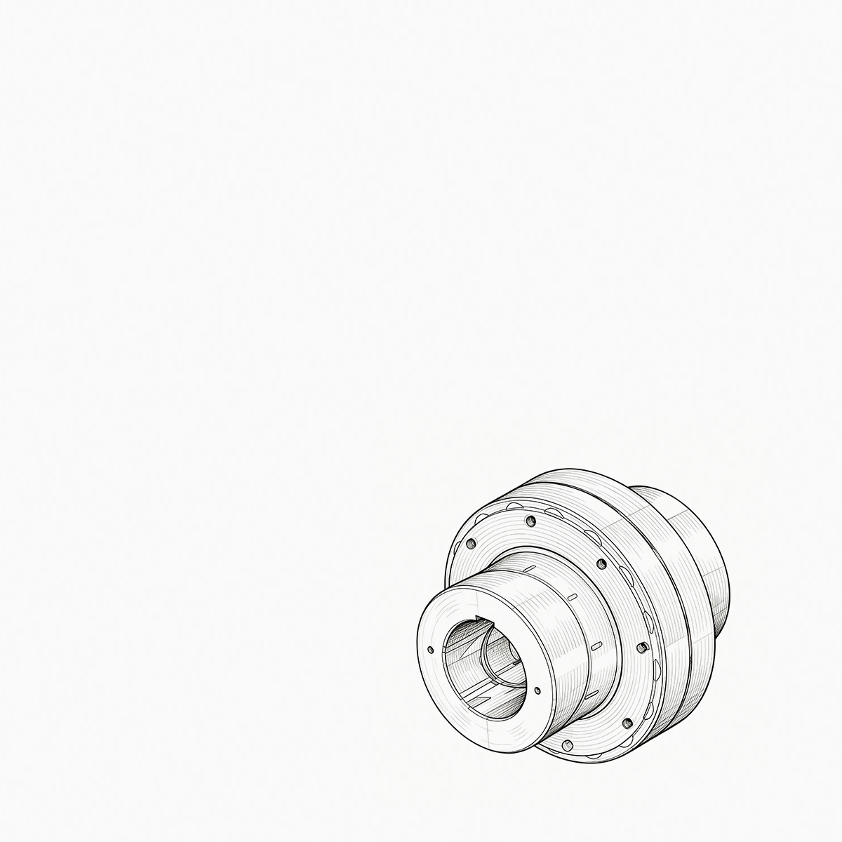
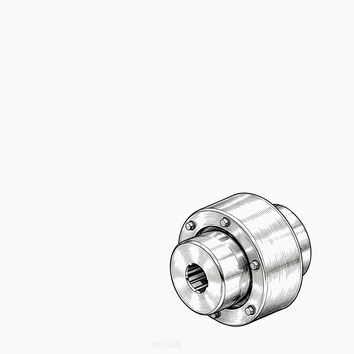
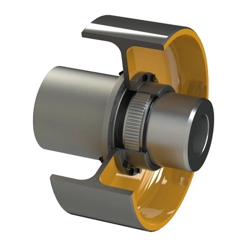
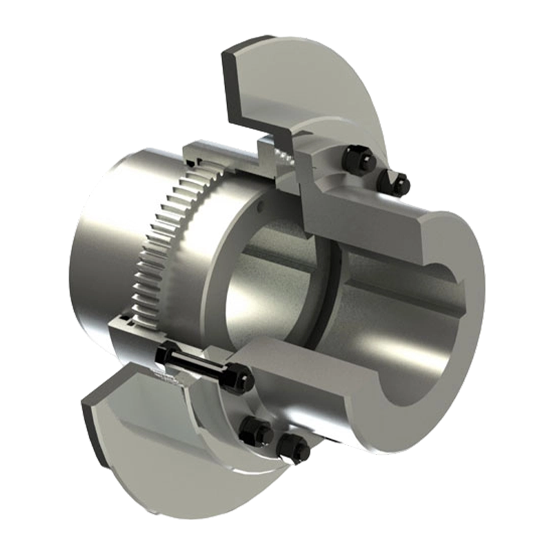
The WGZ Type Crowned-Gear Coupling with Brake Wheel is designed for applications in which high torque transmission and effective braking must be provided within the same mechanical assembly. Based on the crowned-gear coupling principle, the WGZ configuration combines an external gear sleeve, an internal gear ring, sealing assemblies, and an integrated brake drum. The result is a compact power-transmission and braking solution for demanding industrial environments.
Unlike a conventional coupling that performs only the torque-transmission function, the WGZ coupling incorporates a brake wheel or brake drum that can work with a shoe-type braking system. During normal operation, the coupling transmits rotational power between connected shafts. During controlled shutdown or emergency stopping, the brake shoes act on the drum to generate braking torque and interrupt power transmission. This integrated arrangement can simplify equipment layout, reduce the number of separate components, and support a more coordinated machine design.
The key transmission feature is the crowned tooth profile. The external gear teeth are machined on a spherical surface, with the spherical center arranged in relation to the shaft axis. This geometry enables the coupling to accommodate radial, axial, and angular displacement more effectively than a basic straight-tooth gear coupling. When shaft positions change under load, thermal expansion, foundation movement, or installation tolerance, the crowned teeth help maintain a more favorable contact pattern and reduce the risk of edge loading.
Manufactured and supplied by Zhenjiang Orienthold Machinery Co., Ltd., the product is supported by an organization specializing in industrial couplings and papermaking machinery. The company integrates product design, machining, assembly, inspection, and technical service. Its equipment and quality supervision system are intended to support stable production for customers in transportation, metallurgy, chemical engineering, mining, construction, and hoisting.
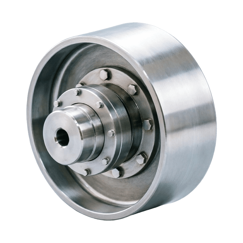
WGZ Type Crowned-Gear Coupling with Brake Wheel
What Is a WGZ Crowned-Gear Coupling?
A WGZ crowned-gear coupling is a flexible mechanical coupling with an integrated brake drum. It connects two shafts while allowing a controlled degree of relative movement between them. The coupling transmits torque through the engagement of external crowned teeth and an internal gear ring. At the same time, the brake drum provides a friction surface for an external shoe-type brake.
The coupling is commonly installed between a drive motor, gearbox, drum, wheel, winch, conveyor drive, or other rotating machine element. Depending on the system design, it may be used on a high-torque shaft where rapid and dependable stopping is required. Because the coupling and brake function are combined, the equipment designer can reduce the space occupied by separate transmission and braking components.
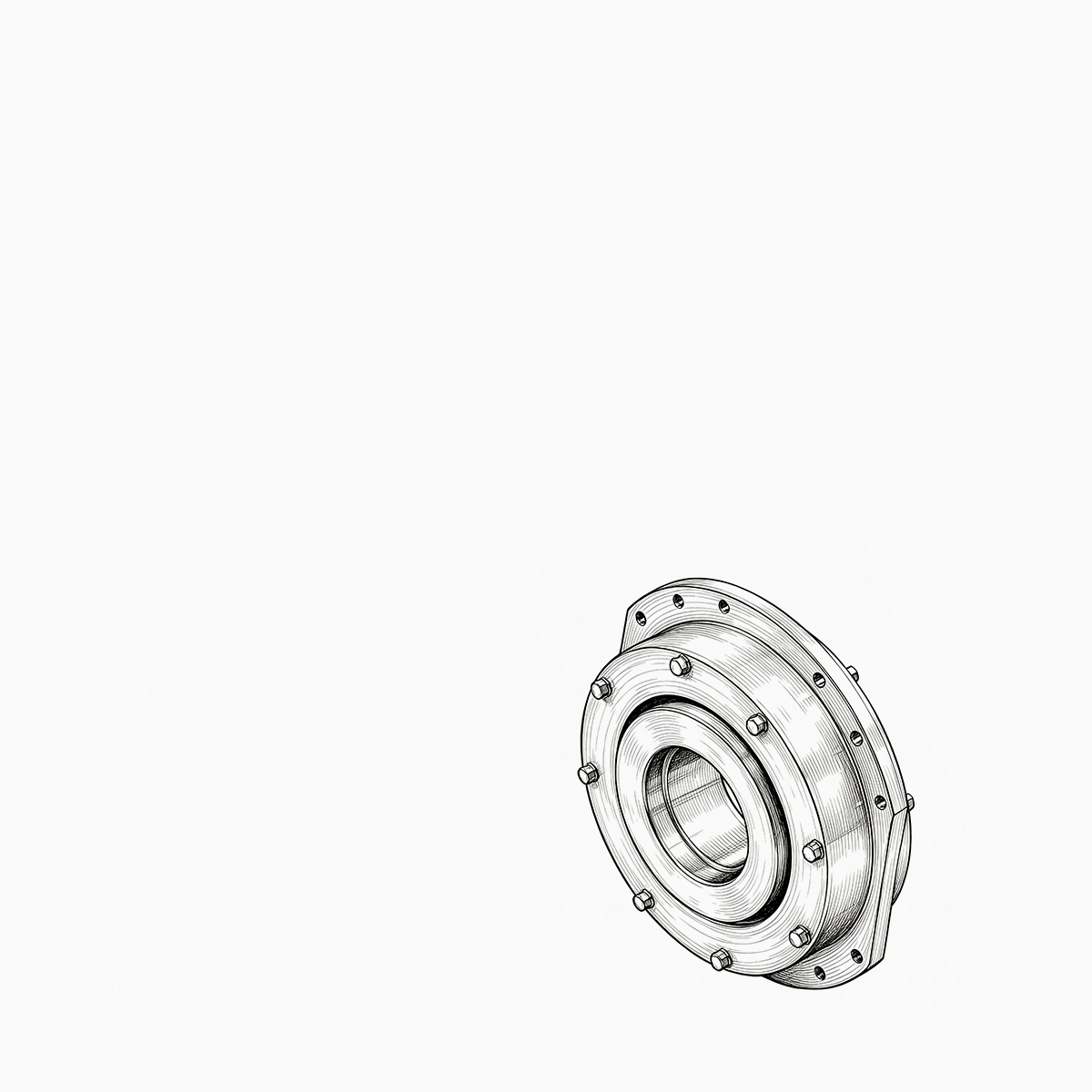
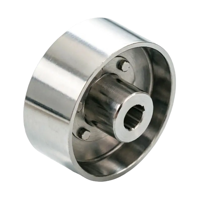
The primary components generally include an external gear sleeve, an internal gear ring, a brake drum, sealing assemblies, fastening elements, and related hubs or connection sections. The external gear sleeve and internal gear ring form the flexible torque-transmission interface. The brake drum is rigidly connected to the coupling body and provides the working surface for the braking shoes.
In operation, torque flows from one shaft through its connected hub into the gear coupling. The external and internal teeth remain engaged while allowing limited relative displacement. The second hub receives the transmitted torque and drives the connected machine. If the drive must stop, the shoe-type brake applies pressure to the outer surface of the brake drum. Friction between the brake shoes and drum produces a counter-torque that slows and stops the rotating system.
The crowned-tooth design is particularly important because industrial shaft systems rarely remain perfectly aligned under all conditions. A shaft may be aligned accurately during installation but experience displacement when the machine is loaded, heated, cooled, or subjected to vibration. Bearings may settle, foundations may move slightly, and connected equipment may produce changing reaction forces. The coupling must therefore provide controlled flexibility without compromising torque capacity.
Integrated Transmission and Braking Function
The most distinctive advantage of the WGZ Type Crowned-Gear Coupling with Brake Wheel is the integration of two essential machine functions. A conventional layout may require a separate flexible coupling and an independently mounted brake wheel or brake disc. Each component needs space, supports, guards, alignment work, and maintenance access. The WGZ design combines these functions in one coordinated assembly.
This integration can produce a more compact system arrangement. In hoisting machinery, where the available installation space is often restricted, reducing the axial length and number of individual components can simplify the design of the drive train. A compact arrangement may also make it easier to position the motor, reducer, drum, and brake in relation to the supporting frame.
Combining the coupling and brake drum can also reduce the number of interfaces between components. Every additional shaft connection, hub, key, flange, or support introduces another point that must be designed, aligned, inspected, and maintained. An integrated coupling reduces some of this duplication and allows the transmission and braking functions to be considered together.
The integrated structure does not eliminate the need for correct brake selection. The brake shoes, brake actuator, braking torque, heat dissipation, duty cycle, stopping time, and emergency requirements must still be evaluated by the equipment designer. However, the WGZ coupling provides a purpose-designed brake drum that can be matched with a suitable shoe-type braking system.
During normal operation, the brake drum rotates together with the coupling body. During braking, the shoes apply friction to the drum. The braking action can be used for normal stopping, positioning, holding, or emergency interruption, depending on the complete machine design. Correct adjustment of shoe clearance and brake force is essential for reliable performance and to avoid unnecessary heat generation.
Compared with a separately assembled brake wheel, the integrated design can improve layout rationality and reduce the risk of mismatched components. The coupling and drum are produced as part of one product concept, allowing the mechanical relationship between torque transmission and braking to be established during design and manufacturing.
Crowned Tooth Profile and Misalignment Compensation
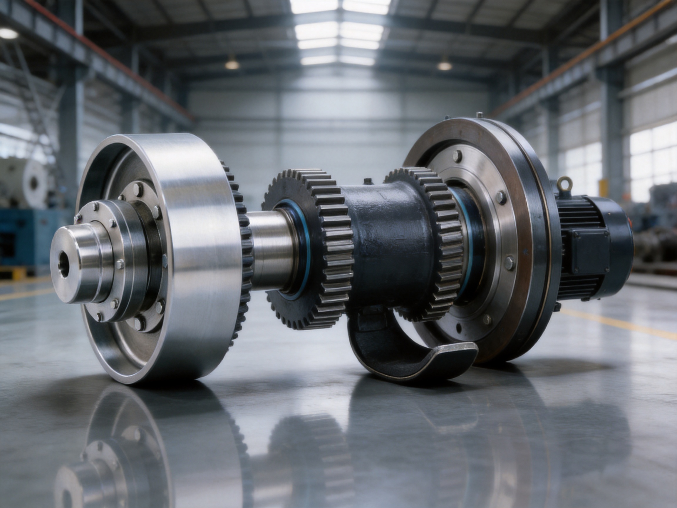
The crowned gear profile is the core feature that distinguishes this type of coupling from a simple straight-tooth gear coupling. In a crowned gear coupling, the external tooth surface is formed with a spherical or barrel-shaped curvature. This allows the tooth engagement to remain more favorable when the connected shafts are not perfectly collinear.
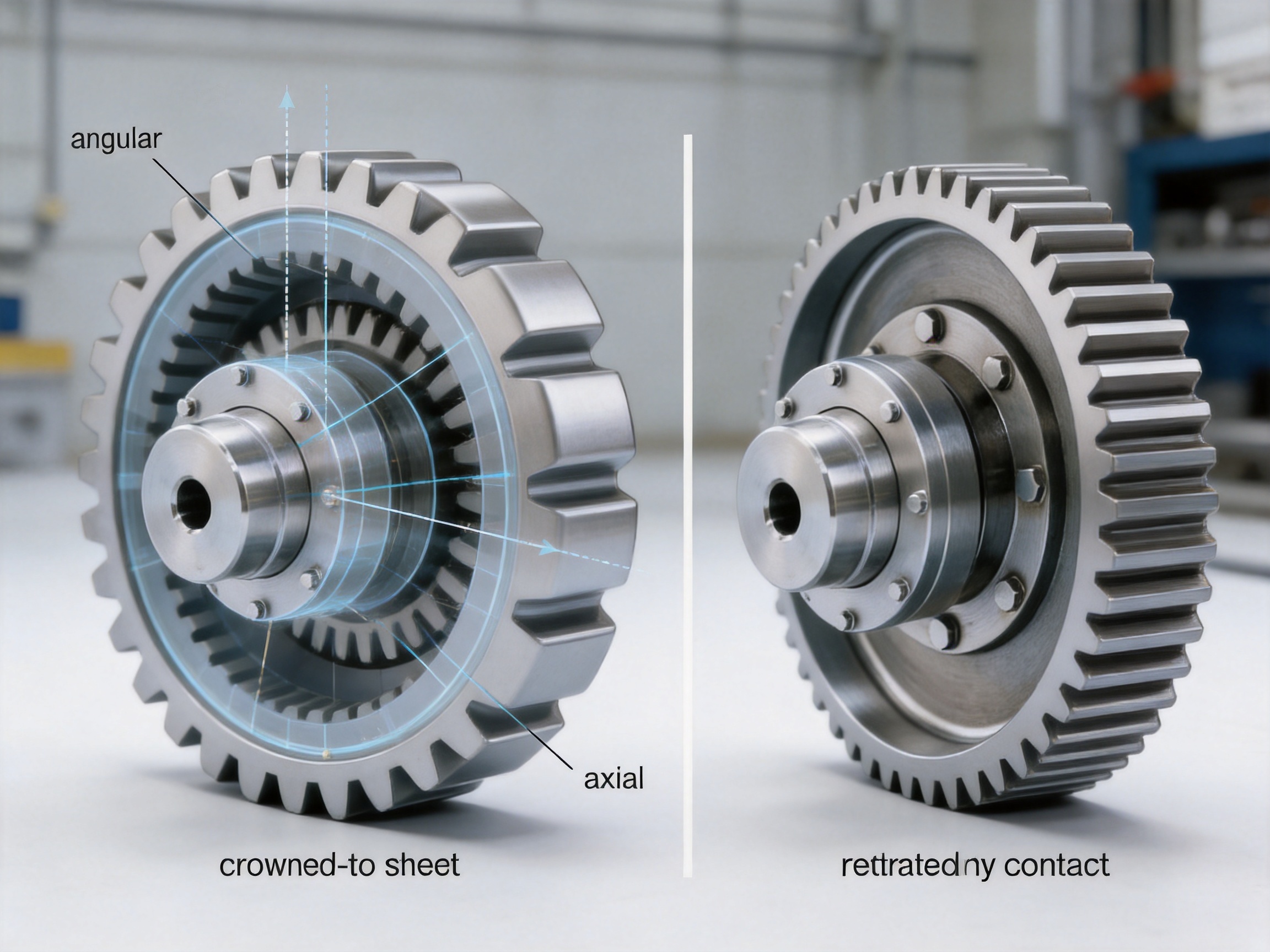
Angular misalignment occurs when the centerlines of two shafts intersect at an angle. Radial misalignment occurs when the two shaft centerlines are parallel but offset. Axial movement occurs when the shafts move toward or away from one another. In actual machinery, these forms of displacement may appear individually or simultaneously.
A straight-tooth design generally has less ability to accommodate angular displacement because the tooth flanks can contact unevenly when the shafts tilt relative to one another. Under these conditions, the load may concentrate near a tooth edge. Edge loading increases local stress and can accelerate wear, pitting, scoring, or tooth deformation.
The crowned tooth profile allows the contact area to adjust as the shaft position changes. Rather than relying on a rigid, flat tooth engagement, the curved tooth geometry provides controlled freedom for the coupling to adapt to angular and radial displacement. The contact pattern can therefore remain more evenly distributed, helping reduce localized stress concentration.
This design is not intended to compensate for unlimited misalignment. Every coupling has a specified allowable range, and operation beyond that range can cause excessive tooth pressure, heat, vibration, lubricant loss, and accelerated wear. Proper shaft alignment remains important. The advantage of the crowned profile is that it provides a larger and more reliable tolerance for normal operating displacement.
Greater misalignment tolerance can be especially valuable in heavy industrial equipment. Hoisting systems experience changing loads and structural deflection. Mining machinery may be exposed to vibration and foundation movement. Metallurgical equipment can experience significant temperature variation. Conveying equipment may have long drive lines and multiple support points. In these conditions, a coupling with controlled flexibility can help protect the connected shafts and bearings.
By maintaining a more favorable tooth contact pattern, the crowned design can also improve load distribution. Better load distribution may reduce peak tooth stress and support longer service life when the coupling is correctly selected, lubricated, and maintained. It can also contribute to smoother torque transfer and reduced vibration compared with a poorly aligned straight-tooth arrangement.
Radial Displacement
Radial displacement describes a parallel offset between two shaft centerlines. The displacement may be caused by installation tolerance, bearing movement, thermal expansion, structural deflection, or uneven foundation conditions. The WGZ coupling allows the gear engagement to accommodate a controlled degree of this offset.
Type I, which features a split sealing end and larger tooth spacing, is particularly suitable when greater radial displacement compensation is required. The larger tooth spacing provides additional room for relative movement within the coupling structure. The actual allowable displacement must be determined according to the selected size, operating speed, torque, and manufacturer’s technical data.
Angular Displacement
Angular displacement occurs when two connected shafts operate at a small angle to one another. The crowned tooth profile is designed to maintain engagement while the shafts tilt relative to each other. This reduces the tendency for one edge of the tooth to carry a disproportionate share of the load.
Angular misalignment is common in equipment with flexible frames, long shafts, or changing loads. Although the coupling can accommodate angular movement, initial alignment should still be performed carefully. Misalignment compensation is a protective capability, not a substitute for accurate installation.
Axial Movement
Axial movement occurs along the shaft centerline. It may result from thermal expansion, thrust changes, bearing clearance, or movement within the machine structure. The coupling construction and internal clearances allow controlled axial movement within the specified operating range.
When axial movement is expected, the installer should confirm that the coupling, connected bearings, brake system, and shaft shoulders can work together without creating unintended axial restraint. The complete assembly must be evaluated rather than considering the coupling in isolation.
Type I and Type II Sealing Configurations
The WGZ coupling is available in two sealing configurations: Type I with a split sealing end and Type II with an integral sealing end. The two configurations are intended to address different installation conditions and operating priorities.
| Configuration | Main Structural Characteristic | Primary Advantage | Typical Selection Consideration |
|---|---|---|---|
| Type I | Split sealing end with larger tooth spacing | Greater radial displacement compensation | Suitable for systems where shaft movement and installation tolerance are significant |
| Type II | Integral sealing end with a more compact arrangement | Lower rotational inertia and faster dynamic response | Suitable for limited installation space and applications requiring quicker response |
Type I is often considered when the equipment may experience comparatively greater radial displacement. Its larger tooth spacing supports additional movement within the gear engagement. This can be beneficial in heavy machinery with structural deflection, long operating periods, or variable loads.
Type II provides a more compact structure and lower rotational inertia. Lower rotating mass can support a faster dynamic response during acceleration and deceleration. This configuration may be preferred when the machine has limited installation space or when the drive system requires more responsive speed changes.
Sealing is essential for gear coupling performance. The sealing assemblies help retain lubricant within the tooth chamber and reduce the entry of dust, moisture, and other contaminants. In mining, construction, and metallurgical environments, contamination control is especially important because abrasive particles can accelerate tooth and seal wear.
The choice between Type I and Type II should be based on the machine’s alignment condition, available space, rotational speed, expected dynamic response, maintenance requirements, and environmental exposure. Product selection should also consider the brake arrangement and accessibility for inspection.
Performance Advantages in Heavy-Duty Applications
High Torque Transmission Capability
The gear engagement of the WGZ coupling is designed for high-torque industrial service. Unlike many lightweight flexible couplings intended for small motors and moderate loads, a crowned-gear coupling can provide a robust transmission path for large rotating systems. The gear teeth distribute torque through multiple engaged surfaces, supporting high load transfer when the coupling is correctly sized.
High torque capacity is important in cranes, hoists, conveyors, crushers, rolling equipment, and other machinery where acceleration loads and shock loads may be substantial. The selected coupling must be matched to the motor power, service factor, operating speed, start-stop frequency, braking torque, and driven-machine inertia.
Improved Resistance to Edge Loading
Edge loading is a common concern in gear couplings that operate with angular or radial misalignment. When the load concentrates near a tooth edge, the local contact pressure increases. Over time, this can lead to tooth surface damage and reduced service life.
The crowned tooth profile helps the tooth contact adapt to relative shaft movement. By reducing the likelihood of severe edge contact, it supports more even load sharing and improved tooth durability. This is one of the principal reasons crowned gear couplings are widely considered for heavy industrial equipment.
Compact Equipment Layout
Because the brake drum is integrated into the coupling body, the WGZ design can reduce the need for a separate brake wheel. This can simplify the arrangement of the motor, reducer, shaft, and brake mechanism. A more compact layout may also reduce the size of guards and supporting structures.
Compactness is valuable in crane machinery, winches, hoisting drives, and enclosed equipment where the available space is limited. It may also make the complete system easier to protect from environmental contamination.
Reliable Braking Interface
The brake drum is designed to work with shoe-type brakes. Its dedicated friction surface supports controlled braking when the shoes are correctly selected and adjusted. Integrating the drum with the coupling body establishes a direct mechanical connection between the rotating transmission assembly and the braking interface.
Reliable braking is particularly important in lifting equipment. A controlled stop helps protect personnel, loads, structures, and machinery. Emergency braking capability must always be designed according to applicable safety requirements and the complete equipment risk assessment.
Support for Variable Operating Conditions
Industrial machinery often operates under changing torque, speed, temperature, and load conditions. The coupling must handle repeated starts and stops, transient loads, and alignment changes without excessive wear. The crowned gear configuration and robust mechanical construction provide a suitable foundation for these demanding conditions when the product is correctly specified.
Comparison with Conventional Coupling Arrangements
The WGZ coupling has several advantages over conventional arrangements, although the correct choice depends on the application. A standard straight-tooth coupling may be adequate for a system with accurate alignment and limited displacement. However, it may be less tolerant of shaft angularity and more vulnerable to edge loading when operating conditions change.
A separate coupling and brake wheel arrangement can provide flexibility in component selection, but it requires more installation space and additional alignment work. It may also involve extra shaft connections, support brackets, fastening elements, and maintenance points. The WGZ integrated configuration reduces some of this complexity.
A flexible elastomeric coupling may offer excellent vibration damping and low maintenance for suitable applications, but it may not be appropriate for every high-torque or high-temperature environment. Elastomeric elements can have limitations related to temperature, chemical exposure, aging, and overload. A crowned-gear coupling is generally selected when high torque density, mechanical durability, and controlled misalignment compensation are priorities.
A rigid coupling can transmit torque efficiently but cannot accommodate normal shaft displacement. If used where misalignment exists, it may transfer excessive forces to bearings, shafts, and machine housings. The WGZ coupling provides a degree of flexibility while maintaining a robust gear-based transmission path.
| Coupling Arrangement | Misalignment Capability | Brake Integration | Typical Strength | Typical Limitation |
|---|---|---|---|---|
| WGZ crowned-gear coupling | Controlled radial, axial, and angular compensation | Integrated brake drum | High torque transmission and compact layout | Requires lubrication, sealing inspection, and correct alignment |
| Conventional straight-tooth gear coupling | More limited angular accommodation | Usually separate | Established gear transmission method | Greater sensitivity to edge loading under misalignment |
| Elastomeric coupling | Good flexibility depending on element design | Usually separate | Vibration damping and simple construction | Element limitations under high temperature, chemicals, or severe overload |
| Rigid coupling | Very limited | Separate | Direct torque transmission | Transfers misalignment forces to connected equipment |
| Separate coupling and brake wheel | Depends on coupling type | Independent brake component | Flexible component selection | More installation space, alignment work, and interfaces |
The comparison shows that the WGZ coupling is most valuable when transmission capacity, misalignment compensation, braking, and compactness must be considered together. It is not merely a replacement for every type of coupling; it is a specialized solution for heavy-duty systems where integrated functionality provides a practical advantage.
Applications of the WGZ Coupling
Hoisting and Crane Machinery
Hoisting equipment requires dependable torque transmission and rapid, controlled stopping. The coupling may be applied in crane travel systems, lifting mechanisms, winches, and other drives where the motor and reducer must transmit high torque while working with a shoe-type brake.
Crane structures can deflect under load, and repeated acceleration and deceleration can create changing shaft conditions. The crowned gear profile helps accommodate controlled misalignment, while the integrated brake drum supports a compact drive arrangement.
Conveying Equipment
Large conveyors may use long drive trains, heavy drums, and high-power motors. Shaft alignment can be affected by foundation settlement, frame movement, and changing belt tension. A crowned-gear coupling can help maintain torque transmission when normal operating displacement occurs.
Where the conveyor must stop quickly or hold a load on an incline, the integrated brake wheel can support a suitable braking system. The complete braking design must consider belt tension, transported material, inertia, stopping distance, and backstop requirements.
Mining Machinery
Mining equipment operates in environments characterized by dust, vibration, impact loading, and difficult maintenance access. Crushers, hoists, feeders, conveyors, and large rotating drives require durable components and effective contamination control.
The sealed gear chamber helps protect the tooth engagement when the coupling is correctly maintained. The robust gear structure and misalignment capability are suited to demanding mechanical conditions, while the integrated brake drum can help simplify drive layouts in large machinery.
Metallurgical Installations
Metallurgical equipment may experience high temperatures, heavy loads, vibration, and frequent operating cycles. Rolling equipment, transfer systems, winches, and auxiliary drives require couplings that can transmit torque reliably despite demanding conditions.
When used in elevated-temperature environments, the coupling specification must include suitable lubrication, sealing, installation clearances, and thermal protection. The crowned profile remains valuable because structural and thermal effects can contribute to shaft misalignment.
Large Rotating Systems
Large rotating systems in construction, chemical engineering, paper production, and general industrial processing may require high-capacity shaft connections. The WGZ coupling can be considered where a gear coupling is preferred and a braking function is needed within the same assembly.
Application engineers should evaluate torque, speed, shock factors, duty cycle, stopping requirements, space constraints, and environmental conditions before selecting a product size and configuration.
Manufacturing Process and Quality Strengths
The performance of a heavy-duty coupling depends not only on its design but also on the quality of materials, machining, heat treatment, assembly, sealing, and inspection. Zhenjiang Orienthold Machinery Co., Ltd. operates as a manufacturer integrating design, production, and service. This integrated capability can provide advantages in product consistency, customization, and technical communication.
Engineering and Product Design
The design process begins with understanding the application. Important factors include rated torque, peak torque, rotational speed, shaft diameter, bore arrangement, misalignment, brake torque, operating temperature, installation space, and maintenance access.
For the WGZ coupling, engineering attention is directed toward the relationship between tooth geometry, gear clearance, brake drum dimensions, sealing arrangement, and structural strength. Type I and Type II configurations provide options for different displacement and space requirements.
Design integration is important because the coupling and brake drum must work as one mechanical assembly. The brake drum must have suitable stiffness and surface characteristics, while the gear components must maintain dependable engagement under the expected torque and misalignment conditions.
Precision Machining
Gear coupling performance is strongly influenced by the accuracy of tooth machining. Tooth geometry, pitch, surface finish, concentricity, and runout must be controlled to support even load distribution. The crowned profile must be formed consistently so that the coupling can accommodate displacement without creating abnormal contact.
Machining operations may include turning, boring, milling, gear cutting, drilling, keyway processing, and finishing. Each operation contributes to the final dimensional accuracy of the coupling. Careful process control helps ensure that the internal gear ring, external gear sleeve, hub, and brake drum maintain the required relationship.
Brake drum machining is also important. The drum surface must provide a suitable interface for the brake shoes, with appropriate roundness, runout, and surface condition. Excessive runout can cause uneven shoe contact, vibration, noise, and irregular braking torque.
Material and Heat-Treatment Control
Materials must be selected according to torque, speed, impact loading, wear, and environmental conditions. Gear components require sufficient strength and wear resistance, while the brake drum requires adequate mechanical integrity and a stable friction interface.
Heat treatment may be used to improve hardness, strength, toughness, and resistance to tooth surface wear. The correct process depends on the selected material and product design. Process records and inspection procedures help verify that the required mechanical properties have been achieved.
Assembly and Sealing
During assembly, the gear components, seals, fasteners, and brake drum must be installed with correct clearances and orientation. Incorrect assembly can lead to abnormal tooth contact, lubricant leakage, seal damage, or brake interference.
Sealing assemblies are installed to retain lubricant and protect the tooth chamber from contamination. Correct seal installation is particularly important in dusty or wet operating environments. Assembly personnel must also verify that rotating components move freely and that the brake drum does not contact fixed components before brake application.
Inspection and Testing
Orienthold Machinery emphasizes quality supervision and maintains inspection and testing capabilities for its products. Inspection may include dimensional verification, visual examination, gear accuracy checks, runout measurement, surface inspection, assembly verification, and functional testing according to the product and customer requirements.
Testing helps identify problems before shipment. It also provides confidence that the coupling has been produced according to the approved design. For customized products, inspection requirements can be discussed during the technical quotation and order-confirmation stages.
A systematic quality process is especially valuable for couplings because many performance problems are related to dimensional accuracy, alignment, lubrication, sealing, or assembly rather than the basic concept of the coupling. Manufacturing discipline helps reduce these risks.
Why Choose an Integrated Manufacturer?
Purchasing a coupling from a manufacturer with design, production, and service capabilities can simplify project coordination. Customers can communicate application information directly to the technical team instead of coordinating between unrelated component suppliers.
Orienthold Machinery serves customers in transportation, metallurgy, chemical engineering, mining, construction, hoisting, and related industries. This range of applications supports experience in different operating conditions and equipment layouts.
The company provides more than a standard product supply function. Its services include pre-sales consultation, product customization, logistics coordination, payment options, and maintenance support. These services are valuable when the coupling must be adapted to a particular shaft size, brake arrangement, installation dimension, or operating condition.
Customization may involve bore dimensions, keyways, flange arrangements, brake drum dimensions, sealing configuration, surface treatment, or other application-related details. Any customization should be confirmed through drawings, technical specifications, and inspection requirements before production.
For international customers, clear technical communication is essential. Information such as motor power, rated speed, shaft diameter, shaft extension, torque, service factor, brake torque, misalignment, ambient conditions, and installation drawings helps the manufacturer recommend an appropriate configuration.
Selection Guidelines
Correct selection begins with a complete description of the application. The following factors should be reviewed before ordering a WGZ coupling.
Torque and Service Factor
Determine the rated torque and peak torque transmitted through the coupling. The selection should consider starting torque, impact loads, reversing operation, overload conditions, and the driven machine’s service factor. Selecting only according to motor nameplate power may not adequately represent the actual mechanical duty.
Rotational Speed
Speed affects centrifugal forces, balance, lubrication behavior, heat generation, and brake response. The coupling must be suitable for the operating speed and any overspeed condition that may occur during transient operation.
Shaft and Bore Dimensions
Provide the shaft diameters, shaft lengths, keyway dimensions, end spacing, and connection details. The coupling must fit the shafts without excessive interference or clearance. Shaft shoulders, retaining devices, and installation access should also be reviewed.
Misalignment
Estimate the expected radial, angular, and axial displacement. If the equipment has significant radial movement, Type I may be considered because of its larger tooth spacing. If compactness and lower rotational inertia are more important, Type II may be appropriate.
Braking Requirements
Specify the required braking torque, stopping time, brake type, duty cycle, emergency requirements, and shoe dimensions. The brake drum must be matched to the brake system. The coupling’s braking function should be evaluated as part of the complete safety system, not as an independent component.
Operating Environment
Describe temperature, moisture, dust, corrosive substances, vibration, installation altitude, and maintenance conditions. Environmental information affects sealing, lubricant selection, surface protection, inspection frequency, and material recommendations.
Installation Space
Confirm the available radial and axial space. Type II may be preferred when the structure must be compact. The installer should also ensure that there is enough room for brake shoe adjustment, inspection, lubrication, and eventual replacement.
Installation and Commissioning
Before installation, inspect the coupling, shafts, brake drum, seals, fasteners, and related components. Confirm that there is no shipping damage, contamination, corrosion, or deformation. Verify the product dimensions against the approved drawing.
Clean the shaft surfaces and connection areas. Check shaft runout and alignment before mounting the coupling. Excessive shaft runout can create additional loads even when the coupling itself is correctly manufactured.
Install hubs and gear components according to the manufacturer’s instructions. Avoid striking precision surfaces with unsuitable tools. Ensure that keys, retaining elements, and fasteners are correctly fitted and secured.
Apply the specified lubricant in the correct quantity. Too little lubricant may increase tooth wear and heat, while excessive lubricant can create churning losses or leakage. The lubricant must be compatible with the seals and operating temperature.
After assembly, rotate the system manually if possible. Check for smooth movement, abnormal resistance, interference, or contact between the brake drum and fixed parts. Adjust the brake shoes according to the brake manufacturer’s requirements.
During commissioning, operate the equipment at low speed or under no-load conditions when practical. Observe vibration, noise, temperature, brake release, brake application, and lubricant leakage. Gradually increase the operating load while monitoring the coupling and brake assembly.
Maintenance and Service Practices
Routine maintenance helps preserve the transmission and braking performance of the WGZ coupling. The inspection schedule should be based on operating hours, duty cycle, environment, speed, load, and safety requirements.
Inspect the coupling for lubricant leakage, damaged seals, abnormal noise, excessive vibration, corrosion, and loose fasteners. Check the brake drum for scoring, cracks, excessive wear, uneven contact, or abnormal heat marks.
Monitor the brake shoe condition and clearance. Shoes that remain in contact with the drum during normal operation can generate unnecessary heat and wear. Excessive clearance can delay braking response or reduce braking effectiveness. Brake adjustment should follow the brake system manufacturer’s instructions.
Check lubricant condition and replenish or replace it at the recommended intervals. Contaminated lubricant may contain metal particles, dust, moisture, or degraded additives. Such contamination can accelerate tooth wear and damage seals.
Inspect the tooth engagement when maintenance access permits. Look for pitting, scoring, spalling, plastic deformation, unusual polishing patterns, or localized wear. An uneven contact pattern may indicate misalignment, insufficient lubrication, overload, or incorrect assembly.
Measure vibration and temperature trends where monitoring equipment is available. A gradual increase in vibration or operating temperature may indicate developing tooth wear, imbalance, seal failure, brake interference, or alignment deterioration.
If the equipment experiences an overload, sudden stop, collision, or emergency braking event, inspect the coupling before returning to normal service. Hidden deformation or tooth damage may not be visible during a brief external inspection.
Safety Considerations
The WGZ coupling and brake wheel are rotating machine components and must be guarded during operation. Personnel should not approach the rotating assembly, brake shoes, or coupling housing while the equipment is energized.
Lockout and isolation procedures must be followed before inspection, lubrication, adjustment, or repair. The load must be safely supported before working on hoisting equipment. A brake should not be treated as the only means of securing a suspended load unless the complete system has been designed and approved for that purpose.
Brake surfaces may become hot during frequent or emergency stopping. Allow sufficient cooling time and use suitable protective equipment during inspection. Do not apply unauthorized lubricants to the brake drum or brake shoe friction surfaces.
Replacement seals, fasteners, gear components, and brake parts should meet the required specifications. Substituting unsuitable parts may affect torque capacity, balance, braking performance, or safety.
Q&A
What is the main function of the WGZ Type Crowned-Gear Coupling with Brake Wheel?
Its main function is to transmit torque between two shafts while providing an integrated brake drum for a shoe-type braking system. It combines flexible gear coupling performance with a braking interface in one mechanical assembly.
How does the crowned tooth profile improve performance?
The crowned tooth profile allows the gear contact area to adjust when radial, axial, or angular displacement occurs. This helps reduce edge loading, local stress concentration, and uneven tooth wear compared with a basic straight-tooth arrangement operating under similar misalignment.
Does the coupling eliminate the need for shaft alignment?
No. The coupling accommodates controlled operating displacement, but accurate initial alignment is still necessary. Excessive misalignment can overload the teeth, seals, bearings, shafts, and brake system.
What is the difference between Type I and Type II?
Type I has a split sealing end and larger tooth spacing, making it suitable when greater radial displacement compensation is required. Type II has an integral sealing end and a more compact structure with lower rotational inertia, making it suitable for limited installation space and faster dynamic response.
Can the WGZ coupling be used with any brake?
It is designed to work with shoe-type braking systems, but the brake must be matched to the drum dimensions, required braking torque, speed, stopping duty, and installation arrangement. The complete brake system should be confirmed during technical selection.
Which industries use this type of coupling?
Typical applications include cranes, hoists, conveyors, mining machinery, metallurgical equipment, construction machinery, large rotating systems, and other industrial drives requiring high torque transmission and dependable braking.
What information is needed for product selection?
Important information includes motor power, rated and peak torque, speed, shaft diameter, shaft extension, bore and keyway details, misalignment, brake torque, stopping requirements, environmental conditions, installation space, and operating duty cycle.
Does the coupling require lubrication?
Yes. The gear teeth require suitable lubrication to reduce friction, wear, and heat. Lubricant type, quantity, and replacement interval should follow the manufacturer’s technical requirements and be adapted to the operating environment.
How does the integrated brake drum benefit equipment design?
It can reduce the need for a separate brake wheel, save installation space, reduce the number of mechanical interfaces, and create a more coordinated arrangement between torque transmission and braking. It may also simplify equipment layout and maintenance planning.
Can the product be customized?
Customization may be possible for shaft connection dimensions, keyways, brake drum details, sealing arrangements, and other application requirements. Customized designs should be confirmed through technical drawings and specifications before production.
What quality capabilities support production?
The manufacturer integrates design, machining, assembly, inspection, and service. Its quality supervision system and inspection equipment support dimensional verification, component inspection, assembly control, and product testing according to product and customer requirements.
How should the coupling be maintained?
Maintenance should include checking lubricant, seals, tooth condition, fasteners, vibration, temperature, brake shoe clearance, and brake drum wear. Inspection frequency should reflect the machine’s load, speed, duty cycle, environment, and safety importance.
Conclusion
The WGZ Type Crowned-Gear Coupling with Brake Wheel is a heavy-duty solution for machinery that requires both robust torque transmission and dependable braking. Its integrated brake drum creates a compact connection between the drive train and shoe-type brake, while its crowned tooth profile provides controlled compensation for radial, axial, and angular shaft displacement.
Compared with conventional straight-tooth couplings, the crowned configuration helps reduce edge loading and improve load distribution when normal operating misalignment occurs. Compared with separate coupling and brake wheel arrangements, the integrated design can simplify equipment layout, reduce component interfaces, and support a more rational mechanical structure.
Type I and Type II configurations allow the product to address different application requirements. Type I emphasizes greater radial displacement compensation, while Type II emphasizes compactness and lower rotational inertia. Careful selection should consider torque, speed, alignment, braking requirements, space, environment, and maintenance access.
The product’s long-term performance depends on more than tooth geometry. Precision machining, material control, heat treatment, sealing, assembly, inspection, lubrication, alignment, and brake adjustment all contribute to reliable operation. Zhenjiang Orienthold Machinery Co., Ltd. supports this product through integrated design and manufacturing capabilities, inspection resources, customization services, and technical support for industrial customers.
For cranes, hoists, conveyors, mining systems, metallurgical equipment, and large rotating machinery, the WGZ coupling offers a practical combination of mechanical flexibility, high-torque transmission, compact construction, and integrated braking. When properly selected, installed, and maintained, it can contribute to safer operation, improved equipment reliability, and a more efficient overall drive-system design.
References
1. Industrial Gear Coupling Design Principles, technical reference literature on crowned tooth geometry, load distribution, and misalignment compensation.
2. Mechanical Power Transmission Engineering, reference material covering torque calculation, service factors, shaft alignment, and coupling selection.
3. Heavy-Duty Crane and Hoisting Machinery Engineering, reference material on drive systems, braking requirements, emergency stopping, and suspended-load safety.
4. Industrial Gear and Flexible Coupling Maintenance Practices, reference material on lubrication, sealing, tooth inspection, vibration monitoring, and service intervals.
5. Machinery Safety and Rotating Equipment Protection Guidelines, reference material on guarding, lockout procedures, brake inspection, and maintenance safety.
6. Manufacturer Technical Documentation for WGZ Type Crowned-Gear Couplings with Brake Wheel, product construction, configuration selection, installation, and maintenance information.
Product: WGZ Type Crowned-Gear Coupling with Brake Wheel
PREV: WGC Type Vertical Crowned-Gear Coupling: Reliable Power Transmission for Vertical Drive SystemsNEXT: SWC-BH Standard Telescopic Welded Universal Coupling: Structure, Performance, and Industrial Applications
Be the First to Know
For exclusive deals and latest offers, sign up by entering your email address below.
Related products
News
-
-
Two quotes land for the same replacement gear coupling: $1,850 from one shop and $2,600 from another. Both promise stan...
READ MORE -
A mill drive rarely fails without warning. It knocks at speed, throws a smear of dark grease around the sleeve flange, ...
READ MORE -
China's coupling industry is at a critical historical juncture of transformation from scale expansion to quality and eff...
READ MORE -
Gear Coupling vs. Drum Gear Coupling: The Core Difference The main difference is that "gear coupling" is a broad catego...
READ MORE -
Industrial Couplings: The Definitive Technical Encyclopedia – Classification, Sizing, Failure Prevention, and Lifecycle...
READ MORE


ABOUT US
PRODUCTS
INDUSTRIES
CONTACT US
- Phone: +86-18652865511
- Email: sales@ohmach.com
- Address: No.1, Minying Developing Zone, Zhenjiang, Jiangsu, China
Copyright Zhenjiang Orienthold Machinery Co., Ltd. All Rights Reserved.
 Custom Industrial Shaft Coupling Manufacturers